


556 photoelectron pulse detectors omission
#optoelectronics
#slotted switch
#H13B1
#556 timer
#pulse detection
#RC components
#photoelectron
#missing pulse detector
#sensor circuit
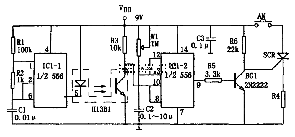
Description: The circuit shown is a photoelectron pulse missing detection circuit. It includes an optoelectronic slotted switch H13B1, a dual time base circuit using a 556 timer IC, and several RC components that form a one-shot multivibrator. The design incorporates a few millimeter-wide slots between the arc tube and the H13B1 photosensitive optoelectronic switch. When an external light-blocking object enters the slot, the internal photodiode beam path of H13B1 is interrupted due to high impedance, causing the pulse signal detector (IC1-2, which is half of the 556 timer) to lack a reset signal. This results in the output transitioning to a temporary steady state. The transient stability time, denoted as td, is determined by the equation td = 1.1R1C2, where W1 can be adjusted to modify td. If the signal interruption lasts longer than the temporary stabilization time, IC1-2 resets, activating the low output enable pin BG1, which causes the SCR to conduct, energizing the corresponding load RL, disconnecting the power supply circuit, or triggering an alarm signal. The multivibrator IC1-1 (the other half of the 556 timer) along with resistors R1, R2, and capacitor C1 determines the oscillation frequency, given by the formula f = 1.44/(R1 + 2R2)C1. The parameters are set to yield an oscillation frequency of approximately 2.5 kHz with a 99% duty cycle, which drives the H13B1 luminous tube.
The photoelectron pulse missing detection circuit is engineered to reliably detect interruptions in light paths, making it suitable for applications where monitoring of light signals is critical. The H13B1 optoelectronic switch serves as a sensitive light sensor, responding to the presence or absence of light within its defined slot. The dual time base circuit, utilizing the 556 timer IC, is pivotal for timing and pulse generation, enabling precise control over the detection and response mechanisms.
The integration of RC components in the one-shot multivibrator configuration allows for flexible timing adjustments. By modifying the resistance values of R1 and R2 or changing the capacitance of C2, the user can calibrate the circuit to accommodate various environmental conditions or specific application requirements. The SCR (Silicon Controlled Rectifier) acts as a switch that can handle high power loads, ensuring that the output response is robust enough to activate alarms or control other devices in response to light interruptions.
The design's high duty cycle of 99% ensures that the H13B1 luminous tube remains illuminated most of the time, providing a clear visual indication of the circuit's operational status. This feature is particularly useful in environments where immediate visibility of the circuit's performance is necessary. Overall, the circuit is a sophisticated solution for detecting light interruptions, offering adjustable timing capabilities and reliable output responses for a variety of applications. As shown in FIG photoelectron pulse missing detection circuit. The detector consists of optoelectronics slotted switch H13B1, dual time base circuit 556 with some RC components constituting the one-shot multivibrator and other components. It opened a few millimeters slots between the arc tube and the photosensitive optoelectronic switch H13B1 tube inside. When the external light blocking object into its slot, H13B1 internal photodiode beam path is cut off due to a high-impedance so IC1-2 (1/2 556) pulse signal detector due to lack of a reset signal and output high into the temporary steady state, transient stability corresponding time td 1.1RwlC2, and adjust W1 can be changed td.
If the signal interruption longer than the temporary stabilization time of magic, the IC1-2 reset, active low output enable pin BG1 end, SCR SCR conduction, so that the corresponding load RL is energized, or the power supply circuit is disconnected, or issue alarm signal. Multivibrator IC1-1 (1/2 556) and R1, R2, C1 and other components, the oscillation frequency of f 1.44/(R1 + 2R2) C1, the icon parameter corresponding oscillation signal frequency of approximately 2.5kHz 99% duty cycle, high duty cycle of the pulse signal driving the H13B1 luminous tube lighting.
The photoelectron pulse missing detection circuit is engineered to reliably detect interruptions in light paths, making it suitable for applications where monitoring of light signals is critical. The H13B1 optoelectronic switch serves as a sensitive light sensor, responding to the presence or absence of light within its defined slot. The dual time base circuit, utilizing the 556 timer IC, is pivotal for timing and pulse generation, enabling precise control over the detection and response mechanisms.
The integration of RC components in the one-shot multivibrator configuration allows for flexible timing adjustments. By modifying the resistance values of R1 and R2 or changing the capacitance of C2, the user can calibrate the circuit to accommodate various environmental conditions or specific application requirements. The SCR (Silicon Controlled Rectifier) acts as a switch that can handle high power loads, ensuring that the output response is robust enough to activate alarms or control other devices in response to light interruptions.
The design's high duty cycle of 99% ensures that the H13B1 luminous tube remains illuminated most of the time, providing a clear visual indication of the circuit's operational status. This feature is particularly useful in environments where immediate visibility of the circuit's performance is necessary. Overall, the circuit is a sophisticated solution for detecting light interruptions, offering adjustable timing capabilities and reliable output responses for a variety of applications. As shown in FIG photoelectron pulse missing detection circuit. The detector consists of optoelectronics slotted switch H13B1, dual time base circuit 556 with some RC components constituting the one-shot multivibrator and other components. It opened a few millimeters slots between the arc tube and the photosensitive optoelectronic switch H13B1 tube inside. When the external light blocking object into its slot, H13B1 internal photodiode beam path is cut off due to a high-impedance so IC1-2 (1/2 556) pulse signal detector due to lack of a reset signal and output high into the temporary steady state, transient stability corresponding time td 1.1RwlC2, and adjust W1 can be changed td.
If the signal interruption longer than the temporary stabilization time of magic, the IC1-2 reset, active low output enable pin BG1 end, SCR SCR conduction, so that the corresponding load RL is energized, or the power supply circuit is disconnected, or issue alarm signal. Multivibrator IC1-1 (1/2 556) and R1, R2, C1 and other components, the oscillation frequency of f 1.44/(R1 + 2R2) C1, the icon parameter corresponding oscillation signal frequency of approximately 2.5kHz 99% duty cycle, high duty cycle of the pulse signal driving the H13B1 luminous tube lighting.
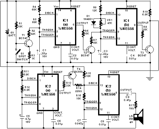
Telephone Ringer using 556 dual timers
Telephone ringer utilizing 556 dual timers. This circuit generates ringing tones resembling those of a telephone by employing modulated rectangular waves of varying time periods.
The telephone ringer circuit employs two 556 dual timer ICs configured to generate modulated rectangular waveforms....

Schematic Diagram Basic Levitation and Magnetic Levitation Circuit Project
This optodetector measures the position of the ball by the amount of light transmitted by the infrared LED. It generates a linear signal across the small area of the detector, rather than simply providing an "on" or "off" output. The...
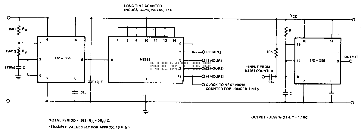
Long time delay
In the 556 timer, the timing is determined by the charging rate of the external capacitor. For prolonged time delays, capacitors with extremely low leakage are necessary, which can be costly. The practicality of the components involved restricts the time...
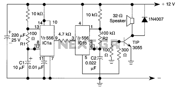
Warble Alarm Circuit
This circuit utilizes a 556 timer IC to initially generate a low-frequency square wave, which is then modulated to produce two alternating tones of approximately 400 Hz and 500 Hz. The circuit is designed to create a warble alarm similar...
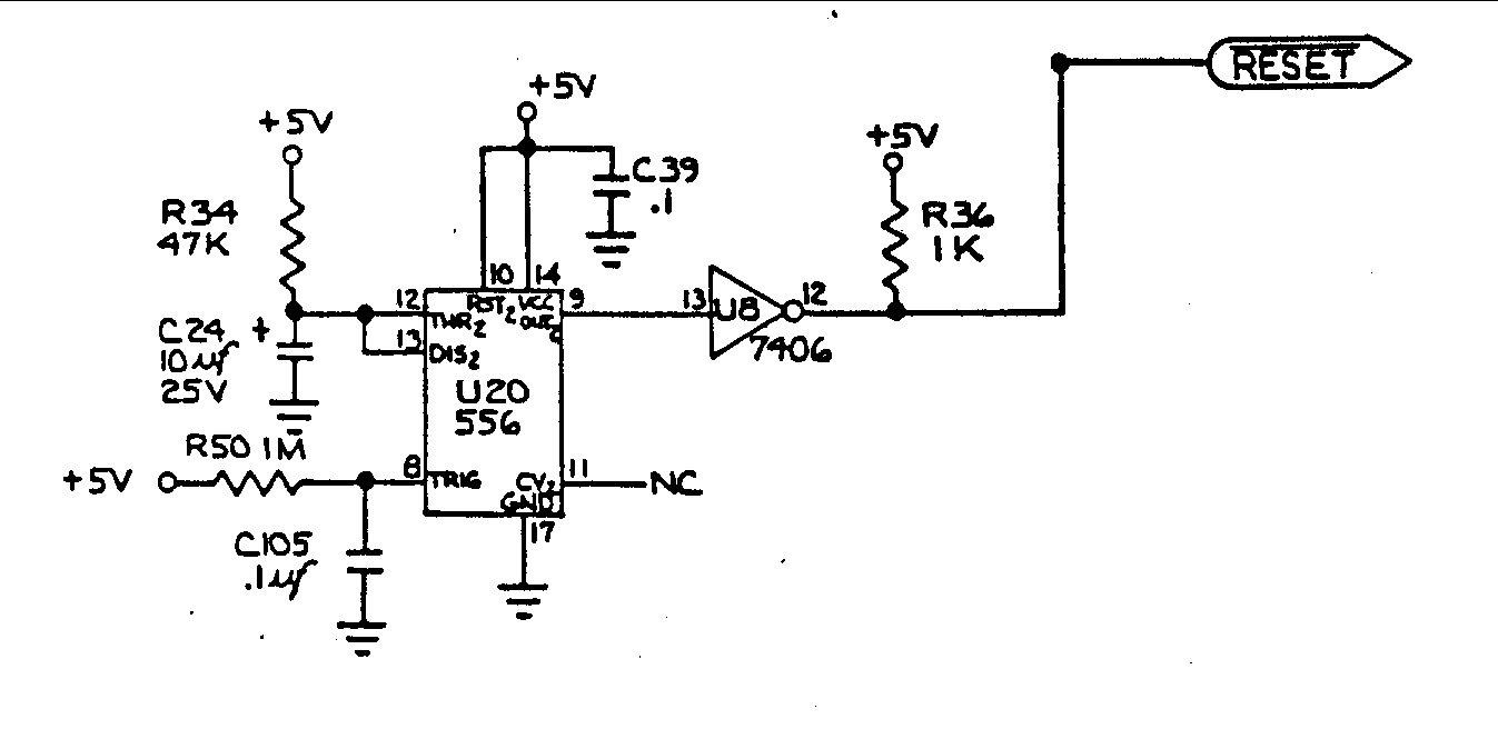
Commodore 64 Reset Logic
U20 is a 556 timer configured as a one-shot multivibrator. The output pulse width is determined by the values of R34 and C24, calculated as Pulse width = 1.1 x R34 x C24, resulting in a duration of 0.5 seconds....
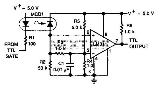
Digital transmission isolator
An optoelectronics device is utilized to couple a digital (TTL) signal to another system. The photodiode within the optocoupler drives an LM311 configured to generate a TTL-compatible output. This configuration is particularly beneficial in scenarios where grounds cannot be connected...

556 controls temperature and liquid level
One-half of a 556 dual timer monitors the temperature of a liquid bath, controlling a heating element that maintains temperature within ±2°C over a 32° - 200°C range. The other half monitors the liquid level, disconnecting the heater when the...
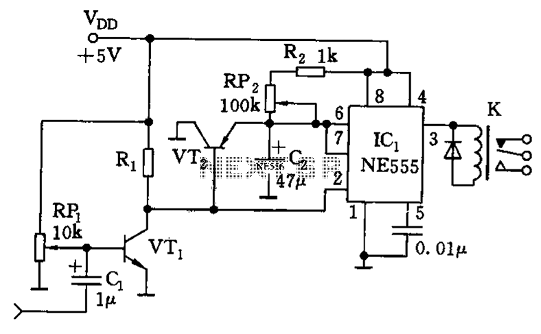
4h 556 composed of a timing circuit diagram
The timing circuit utilizes the 556 dual time base circuit, which includes an intermediate access N8281 crossover network. This design does not require a large volume capacitor, allowing for extended time delays. Initially, the first half of the 556 operates...
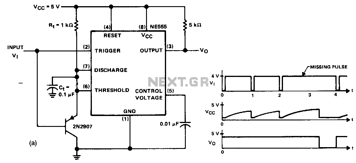
Missing-pulse-detector
This circuit detects a missing pulse or an abnormally long interval between consecutive pulses in a pulse train. The timer is configured in monostable mode, with the time delay set slightly longer than the duration of the input pulses. The...