


BC548 Heat Sensor Diagram Circuit
#heat sensor
#thermistor
#BC548
#potential divider
#temperature coefficient
#NTC
#control circuit
#temperature monitoring
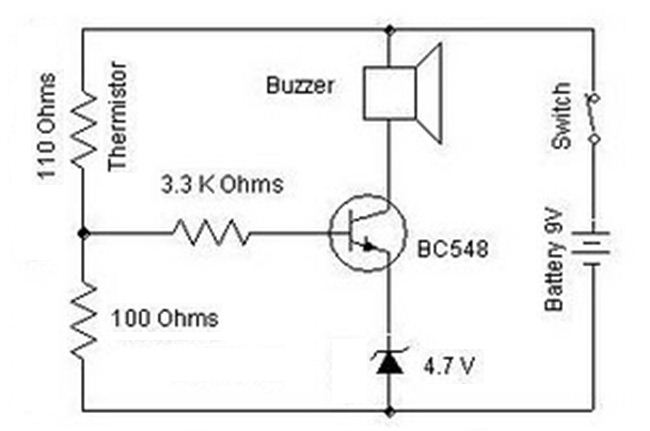
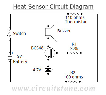
Description: A heat sensor circuit can be utilized to control any device using a heat sensor. In this circuit, a thermistor and a resistor are connected in series, forming a potential divider circuit. The thermistor is of the Negative Temperature Coefficient (NTC) type, meaning that as the room temperature increases, its resistance decreases correspondingly, allowing more current to flow through both the resistor and the thermistor. The resistance value of the thermistor is initially 110 ohms. If the resistance decreases to 90 ohms due to heating, the voltage across one resistor in the voltage divider circuit is determined by the ratio of that resistor's value to the total resistance of the series combination. This illustrates the concept of a voltage divider. The final output voltage from the voltage divider circuit is then applied to an NPN transistor (BC548) through a base resistor of 3.3 kΩ. In this configuration, the emitter resistor is substituted with a Zener diode, which maintains the emitter voltage at 4.7 volts. This voltage is used for comparison purposes. The transistor will conduct when the base voltage exceeds the emitter voltage, specifically when it receives more than 4.7 volts at the base. Once the transistor conducts, the circuit is completed, activating a buzzer that produces sound.
The heat sensor circuit operates on the principle of temperature-dependent resistance changes in the thermistor. The NTC thermistor is critical in this design, as it allows for the detection of temperature variations. As the ambient temperature rises, the decrease in thermistor resistance leads to an increase in current through the potential divider, resulting in a higher voltage at the junction of the thermistor and resistor. This voltage is crucial for controlling the transistor.
The BC548 NPN transistor serves as a switching element in the circuit. The base resistor of 3.3 kΩ limits the current into the base of the transistor, ensuring that it operates within safe parameters. The use of a Zener diode for the emitter stabilizes the voltage, providing a reliable reference for the base-emitter junction. When the input voltage at the base exceeds 4.7 volts, the transistor enters saturation, allowing current to flow from the collector to the emitter, thus activating the buzzer.
This circuit is versatile and can be adapted for various applications, such as temperature alarms, automatic fans, or other devices that require temperature monitoring and control. The design is straightforward and can be implemented with minimal components, making it suitable for educational projects or practical applications in temperature-sensitive environments.Heat sensor circuit can be used to control any device using heat sensor. In this circuit a thermistor and a resistance is connected in series. This arrangement makes a potential divider circuit. Here the thermistor is Negative Temperature Coefficient type. So when the room temperature is increased its resistance decreases simultaneously and more c urrent flows through the resistor and the thermistor. We find more voltage at the junction of the resistor and the thermistor. Our thermistor resistance value is 110 ohms. Suppose the resistance value becomes 90 ohms after heating the 110 ohms thermistor. Then the voltage across one resistor of the voltage divider circuit equals the ratio of that resistor`s value and the sum of resistances of the voltage across the series combination. This is the concept of voltage divider. The final output voltage of the voltage divider circuit is now applied to the npn transistor (BC548) through the base resistor (3.
3K ohms). Here the emitter resistor is replaced with a zener diode. Emitter voltage is maintained at 4. 7volt with the help of zener diode. This voltage is used to compare voltage. Transistor conducts when base voltage is greater than the emitter voltage. Transistor conducts if it gets more than 4. 7volt of base voltage. Then the circuit is completed through buzzer and it gives sound.
The heat sensor circuit operates on the principle of temperature-dependent resistance changes in the thermistor. The NTC thermistor is critical in this design, as it allows for the detection of temperature variations. As the ambient temperature rises, the decrease in thermistor resistance leads to an increase in current through the potential divider, resulting in a higher voltage at the junction of the thermistor and resistor. This voltage is crucial for controlling the transistor.
The BC548 NPN transistor serves as a switching element in the circuit. The base resistor of 3.3 kΩ limits the current into the base of the transistor, ensuring that it operates within safe parameters. The use of a Zener diode for the emitter stabilizes the voltage, providing a reliable reference for the base-emitter junction. When the input voltage at the base exceeds 4.7 volts, the transistor enters saturation, allowing current to flow from the collector to the emitter, thus activating the buzzer.
This circuit is versatile and can be adapted for various applications, such as temperature alarms, automatic fans, or other devices that require temperature monitoring and control. The design is straightforward and can be implemented with minimal components, making it suitable for educational projects or practical applications in temperature-sensitive environments.Heat sensor circuit can be used to control any device using heat sensor. In this circuit a thermistor and a resistance is connected in series. This arrangement makes a potential divider circuit. Here the thermistor is Negative Temperature Coefficient type. So when the room temperature is increased its resistance decreases simultaneously and more c urrent flows through the resistor and the thermistor. We find more voltage at the junction of the resistor and the thermistor. Our thermistor resistance value is 110 ohms. Suppose the resistance value becomes 90 ohms after heating the 110 ohms thermistor. Then the voltage across one resistor of the voltage divider circuit equals the ratio of that resistor`s value and the sum of resistances of the voltage across the series combination. This is the concept of voltage divider. The final output voltage of the voltage divider circuit is now applied to the npn transistor (BC548) through the base resistor (3.
3K ohms). Here the emitter resistor is replaced with a zener diode. Emitter voltage is maintained at 4. 7volt with the help of zener diode. This voltage is used to compare voltage. Transistor conducts when base voltage is greater than the emitter voltage. Transistor conducts if it gets more than 4. 7volt of base voltage. Then the circuit is completed through buzzer and it gives sound.
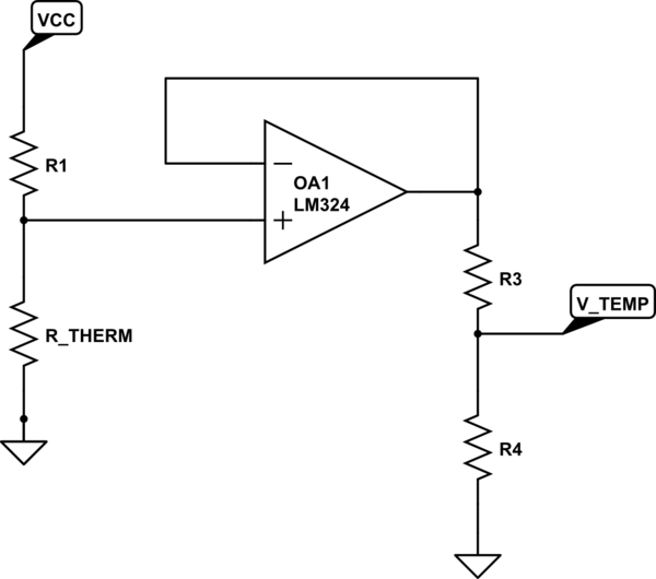
resistance Replicate thermistor behavior for second sensor
An R/C electric motor is equipped with a 10K thermistor sensor, which connects to a speed control unit that includes basic thermal protection. A secondary sensor board is intended to be developed to display the temperature on a segment display...
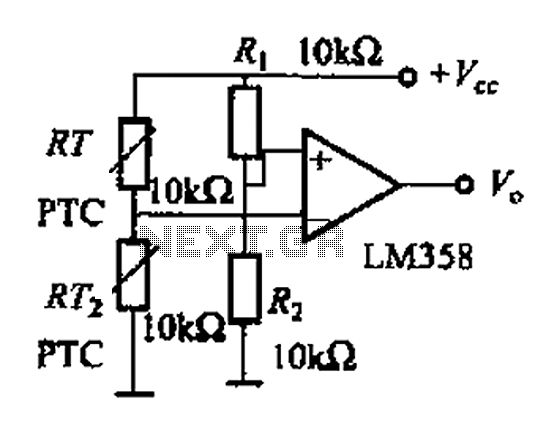
Thermistor basic application circuit b
The basic application circuit for a thermistor is illustrated. Figure (a) depicts a fundamental temperature measurement circuit with limited accuracy, suitable only for applications that do not require high precision. RT represents a positive temperature coefficient thermistor; as the temperature...
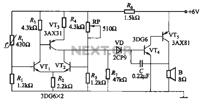
Over-temperature alarm circuit
A negative temperature coefficient thermistor is utilized as the temperature sensing element (Rt). The circuit includes a resistor (Ri), a resistor (Rs), a potentiometer (RP), and the thermistor (R) to form a temperature bridge. A differential amplifier is created using...
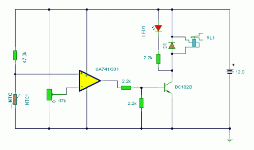
temperature monitor
A thermistor placed in the specified position creates a heat-activated sensor. Variations in temperature will modify the output of the operational amplifier (op-amp), activating the relay and illuminating the LED. Interchanging the positions of the thermistor and the 47k resistor...
Heat Sensor
This simple heat sensor circuit can detect heat from various electronic devices such as computers and amplifiers, generating a warning alarm when overheating occurs. It can also sense heat from the environment, but it is primarily designed for use in...
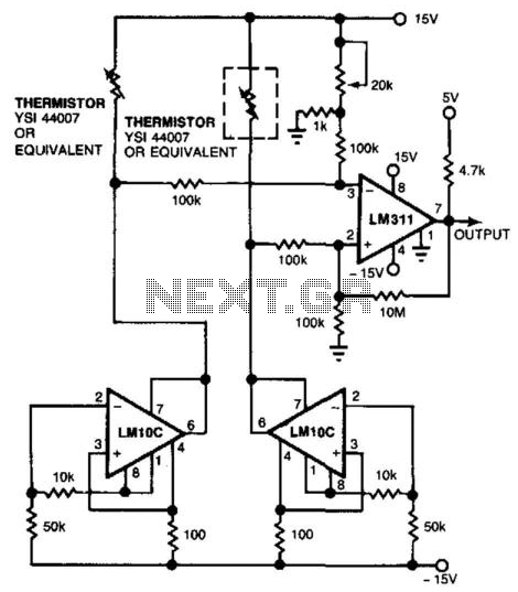
Air-Flow Sensing Thermistor Bridge
Using a thermistor-bridge circuit, it is possible to detect air losses in system cooling caused by filter or inlet blockage or fan failure. One thermistor is placed directly in the airflow, while the other is shielded. The exposed thermistor measures...
Simple-linear-thermometer
The thermistor network specified eliminates the need for a linearity trim at the expense of accuracy and operational range.
The thermistor network is designed to provide a simplified approach to temperature measurement and compensation by negating the requirement for linearity trimming....
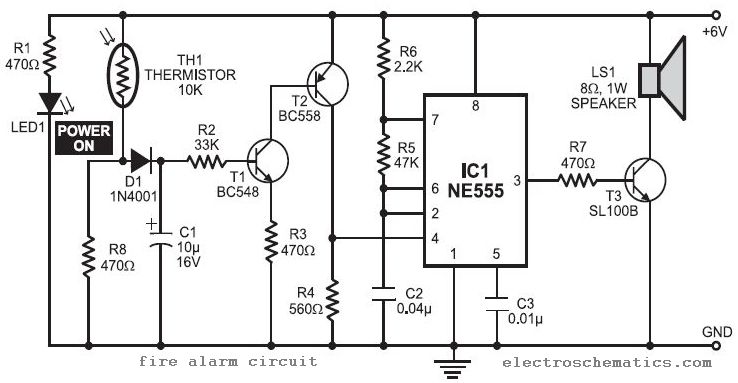
Fire Alarm Circuit
In this fire alarm circuit project, a thermistor functions as the heat sensor. When the temperature rises, its resistance decreases, and conversely, when the temperature falls, its resistance increases. Under normal conditions...
In this fire alarm circuit, the thermistor is a...
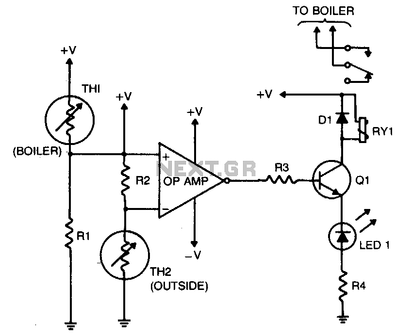
Boiler control
The purpose of this circuit is to control the water temperature in a hot-water heating system. It lowers the boiler temperature as the outside air temperature increases. An operational amplifier (op-amp) is utilized as a comparator. Thermistor TH2 and resistor...