


Bias supply powers low power Geiger Mueller tube
#Geiger Mueller tube
#radiation detection
#bias supply
#low power
#pulse width
#gamma-ray
#dose-rate
#sensor circuit
#radiation field
#quick detection
Description: Pulse size and width are independent of pulse energy or other properties of the event. Geiger-Mueller tubes have reduced sensitivity to non-gamma-ray radiation and exhibit poor dose-rate calibration accuracy. They are commonly used due to their favorable balance of cost, performance, and size for applications requiring rapid detection of radiation fields and rough estimations of their levels. A significant drawback of Geiger-Mueller tubes is their high bias voltage, which ranges from 350V to 900V, depending on the tube design and gas mixture. Ideally, a specific tube should be biased to operate in the center of its plateau, a region of 100V to 150V where the counting rate remains relatively stable with varying bias voltage, assuming a consistent radiation field. The miniaturization of portable radiation monitors is constrained by the tube size, which influences sensitivity, and the duration of operation between battery replacements or recharges. Beyond the high-voltage supply, the radiation-monitor circuitry is generally straightforward, comprising a pulse ratemeter with either an analog or digital readout that displays the radiation dose rate, along with visual or auditory indications of the frequency of radiation events detected by the tube. Some systems may incorporate an integration function to indicate the total dosage since the last reset. These circuits can be designed in micropower versions, extending the operational period between battery charges. However, the high-voltage power supply introduces challenges. A significant portion of the system's quiescent power consumption occurs in the resistive divider that sets the output-voltage sample. To achieve minimal power consumption, very high-resistance values must be utilized for the upper portion of the divider, often exceeding the maximum 22MΩ available in most standard resistor lines. High-value resistors complicate board design and influence the choice of base material. Additionally, component size is a consideration. A boost converter with a 7-stage voltage-multiplying ladder can address many high-voltage bias supply issues. Since feedback for regulation is drawn only from the lowest stage, standard-value resistors can be employed for the feedback divider, significantly reducing quiescent power consumption. Furthermore, the use of compact magnetics, power devices, and other components allows for a small circuit footprint. Multi-diode packages can further minimize size. The circuit response to changes in input voltage and load current is illustrated in Figures 2-4. Notably, the very low input current (80 μA) in the no-load condition (absence of radiation) is critical, as this represents the operating condition nearly 100% of the time. The Geiger-Mueller tube extracts a small charge from the power supply with each radiation event, meaning that the current drawn from the bias supply correlates with the frequency of events (dependent on radiation level) multiplied by the charge per event.
The Geiger-Mueller tube operates by detecting ionizing radiation through the ionization of gas within the tube. When radiation enters the tube, it ionizes gas molecules, creating electron-ion pairs. A high voltage applied across the tube electrodes causes these electrons to accelerate towards the anode, leading to further ionization and an avalanche effect, resulting in a measurable pulse. The design of the pulse ratemeter is crucial, as it must accurately count these pulses and convert them into a readable format, either analog or digital. The choice of components in the circuitry should prioritize low power consumption, especially in portable applications where battery life is critical.
To enhance the functionality of the radiation monitor, integrating features such as a digital display for dose rate and total dosage can provide users with real-time information. Additionally, implementing a microcontroller can facilitate more complex operations, such as data logging, alarm systems for high radiation levels, and user interface improvements. The integration of low-power components throughout the design will ensure that the device remains operational for extended periods without frequent battery changes, making it suitable for field applications.
In conclusion, the design considerations for a portable radiation monitor utilizing a Geiger-Mueller tube involve balancing sensitivity, power consumption, and size. The use of advanced circuit techniques, such as voltage multiplication and efficient feedback mechanisms, can significantly enhance performance while minimizing the overall footprint of the device.Pulse size and width are independent of the pulse energy or other properties of the event. Geiger-Mueller tubes are less sensitive to non-gamma-ray radiation, and their dose-rate calibration accuracy is poor. They are widely used because they offer a good compromise in cost/performance/size for applications that require quick detection of a radiation field and a rough
estimate of its level. One problem with Geiger-Mueller tubes is their high bias voltage, which is 350V to 900V depending on the tube design and the mixture of gases used. Ideally, a given tube is biased to operate in the center of its plateau, a region of 100V to 150V in which the counting rate varies little with bias voltage (assuming a stable radiation field).
The miniaturization of a portable radiation monitor is limited by the size of the tube, which defines sensitivity, and the amount of operating time between battery replacements or rechargings. Aside from the high-voltage supply, radiation-monitor circuitry is relatively simple: a pulse ratemeter with analog or digital readout (indicating the radiation dose rate), and a visual or audio indication of frequency for the radiation events striking the detector tube.
Some systems include an integration function that indicates the total dosage since last reset. These circuits are easily designed in micropower versions that allow a longer period of operation between battery charges. The HV power supply, however, poses problems. A large portion of the system`s quiescent power consumption occurs in the resistive divider that sets the output-voltage sample.
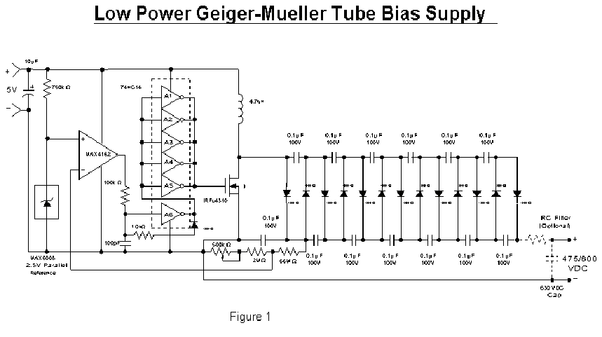
For absolute-minimum power consumption, you must use very high-resistance values for the top portion of the dividerway beyond the maximum 22M available in most standard resistor lines. High-valued resistors complicate the board design and the choice of base material for the board. Component size is also an issue. A boost converter with 7-stage voltage-multiplying ladder (Figure 1) solves many problems of the HV bias supply.
Because feedback (for regulation) is taken only from the lowest stage, you can use standard-value resistors for the feedback divider, which reduces the quiescent power consumption by a large factor. And because the magnetics, power devices, and all other components are tiny, the circuit can be built very small.
Multi-diode packages can reduce the size even further. Figures 2-4 show the circuit response to changes in input voltage and load current. Of particular interest is the very low input current (80 A) in the no-load condition (no radiation present), which for this application is the operating condition almost 100% of the time. The Geiger-Muller tube takes a small amount of charge from the power supply each time it is hit by a radiation event.
Current taken from the bias supply therefore equals the frequency of events (radiation-level dependent) times the per-event charge.
The Geiger-Mueller tube operates by detecting ionizing radiation through the ionization of gas within the tube. When radiation enters the tube, it ionizes gas molecules, creating electron-ion pairs. A high voltage applied across the tube electrodes causes these electrons to accelerate towards the anode, leading to further ionization and an avalanche effect, resulting in a measurable pulse. The design of the pulse ratemeter is crucial, as it must accurately count these pulses and convert them into a readable format, either analog or digital. The choice of components in the circuitry should prioritize low power consumption, especially in portable applications where battery life is critical.
To enhance the functionality of the radiation monitor, integrating features such as a digital display for dose rate and total dosage can provide users with real-time information. Additionally, implementing a microcontroller can facilitate more complex operations, such as data logging, alarm systems for high radiation levels, and user interface improvements. The integration of low-power components throughout the design will ensure that the device remains operational for extended periods without frequent battery changes, making it suitable for field applications.
In conclusion, the design considerations for a portable radiation monitor utilizing a Geiger-Mueller tube involve balancing sensitivity, power consumption, and size. The use of advanced circuit techniques, such as voltage multiplication and efficient feedback mechanisms, can significantly enhance performance while minimizing the overall footprint of the device.Pulse size and width are independent of the pulse energy or other properties of the event. Geiger-Mueller tubes are less sensitive to non-gamma-ray radiation, and their dose-rate calibration accuracy is poor. They are widely used because they offer a good compromise in cost/performance/size for applications that require quick detection of a radiation field and a rough
estimate of its level. One problem with Geiger-Mueller tubes is their high bias voltage, which is 350V to 900V depending on the tube design and the mixture of gases used. Ideally, a given tube is biased to operate in the center of its plateau, a region of 100V to 150V in which the counting rate varies little with bias voltage (assuming a stable radiation field).
The miniaturization of a portable radiation monitor is limited by the size of the tube, which defines sensitivity, and the amount of operating time between battery replacements or rechargings. Aside from the high-voltage supply, radiation-monitor circuitry is relatively simple: a pulse ratemeter with analog or digital readout (indicating the radiation dose rate), and a visual or audio indication of frequency for the radiation events striking the detector tube.
Some systems include an integration function that indicates the total dosage since last reset. These circuits are easily designed in micropower versions that allow a longer period of operation between battery charges. The HV power supply, however, poses problems. A large portion of the system`s quiescent power consumption occurs in the resistive divider that sets the output-voltage sample.
For absolute-minimum power consumption, you must use very high-resistance values for the top portion of the dividerway beyond the maximum 22M available in most standard resistor lines. High-valued resistors complicate the board design and the choice of base material for the board. Component size is also an issue. A boost converter with 7-stage voltage-multiplying ladder (Figure 1) solves many problems of the HV bias supply.
Because feedback (for regulation) is taken only from the lowest stage, you can use standard-value resistors for the feedback divider, which reduces the quiescent power consumption by a large factor. And because the magnetics, power devices, and all other components are tiny, the circuit can be built very small.
Multi-diode packages can reduce the size even further. Figures 2-4 show the circuit response to changes in input voltage and load current. Of particular interest is the very low input current (80 A) in the no-load condition (no radiation present), which for this application is the operating condition almost 100% of the time. The Geiger-Muller tube takes a small amount of charge from the power supply each time it is hit by a radiation event.
Current taken from the bias supply therefore equals the frequency of events (radiation-level dependent) times the per-event charge.
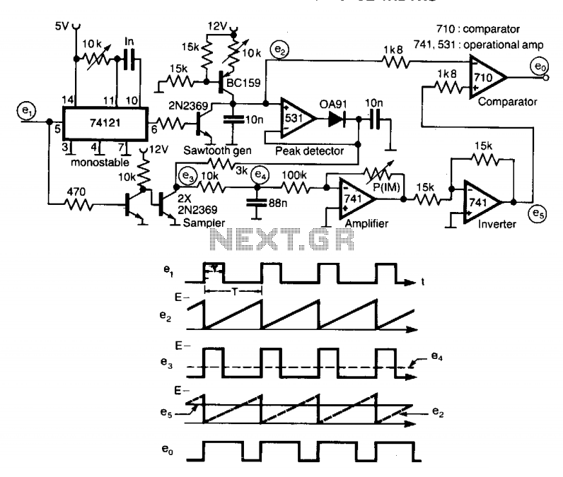
Multiplying pulse widths circuit
A circuit designed to multiply the width of incoming pulses by a factor that can be greater or less than unity is straightforward to construct. It features a single adjustable potentiometer for selecting the multiplying factor. This factor is established...

micro power pulse generator
This circuit generates clean logic pulses with minimal current consumption. It is designed to produce short 2 ms pulses at a frequency of one pulse per second, drawing only 1 microamp from a 9-volt battery.
The described circuit operates efficiently by...
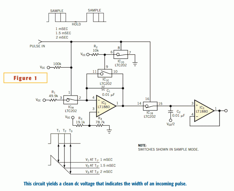
Circuit converts pulse width to voltage
The circuit in Figure 1 converts pulse information to a clean dc voltage by the end of a single incoming pulse. In another technique, an RC filter can convert a PWM signal to an averaged dc voltage, but this method...
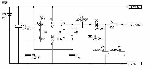
Low Power Negative Car Power Supply
I have had a lot of queries about getting a low power negative supply in cars, to power Linkwitz transform circuits and the like. There is a switchmode converter, but I must admit that it is overkill for what most...
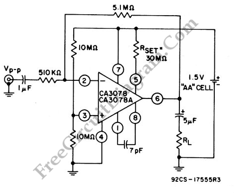
Single Cell Battery 1.5V 20dB Inverting Amplifier
This amplifier circuit exhibits a very low power consumption, with a total current draw of 675 nA. The output voltage swing is 300 mV peak-to-peak (pp) with a gain of 20.
The amplifier circuit is designed to operate with minimal power...
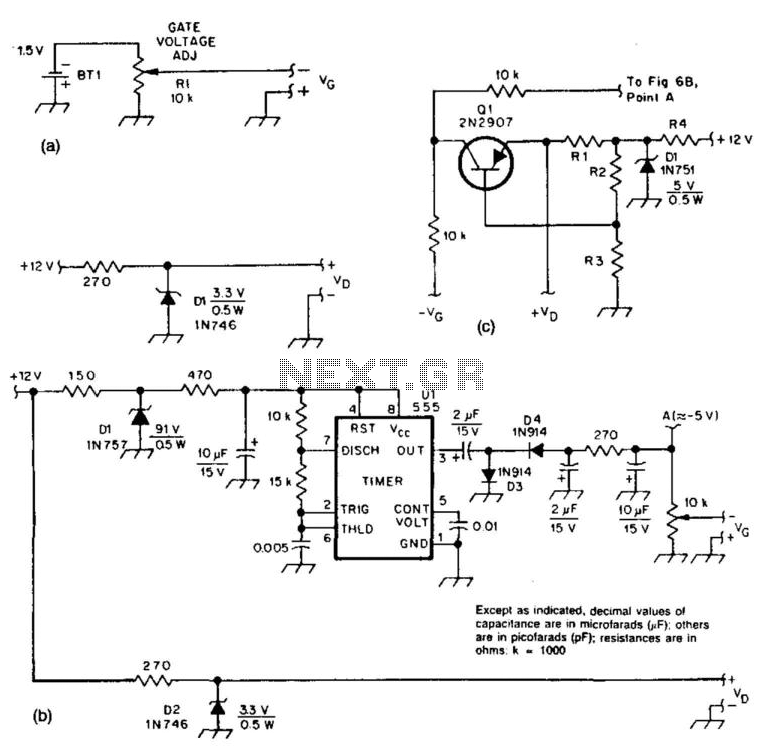
Bias Supply For Microwave Preamps
These two circuits provide bias for the microwave preamplifiers discussed in this text. The circuit in Figure 51-5(a) is a simple passive power supply. Figures 51-5(b) and 51-5(c) represent active power supplies, with Ul generating a negative supply and Ql...
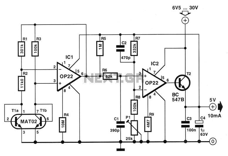
Low Power consumption 5V regulator circuit
The circuit described below is notable for its low power consumption. With a 9V input and no load at the output, it draws only 50 mA, which is significantly lower than the quiescent current of a 78L05 regulator. The circuit...
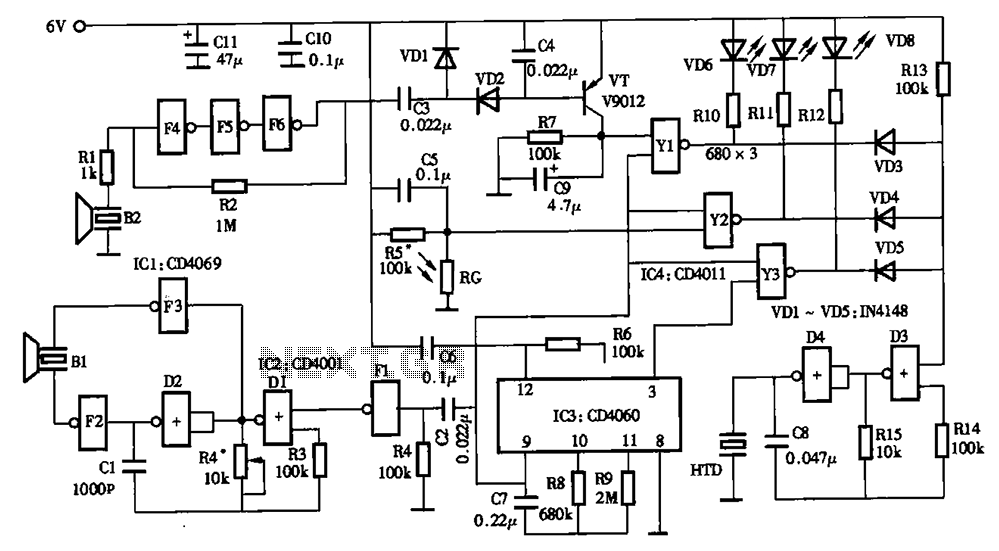
Low power timer switch
The timing circuit utilizes an electronic switch composed of F1, F2, and VT1 to reduce quiescent current to approximately 1 to 2 A with the 555 timer. Upon initial power-up, the voltage across capacitor C2 cannot instantly change, causing the...
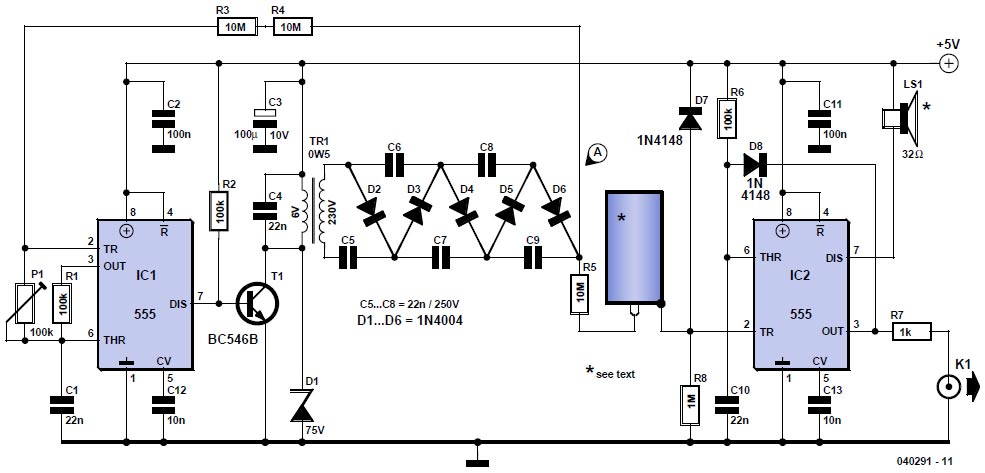
Geiger Counter
April 2006 marked the twentieth anniversary of the Chernobyl reactor accident. In the aftermath of the incident, winds dispersed much of the reactor's contents across central Europe, Scandinavia, and the UK. A large area surrounding the reactor remains restricted, raising...