


Clear Glass Sensor Circuit
#glass sensor
#ultra bright LED
#photodiode
#experimental
#hobby project
#sensor unit
#light detection
#DIY sensor
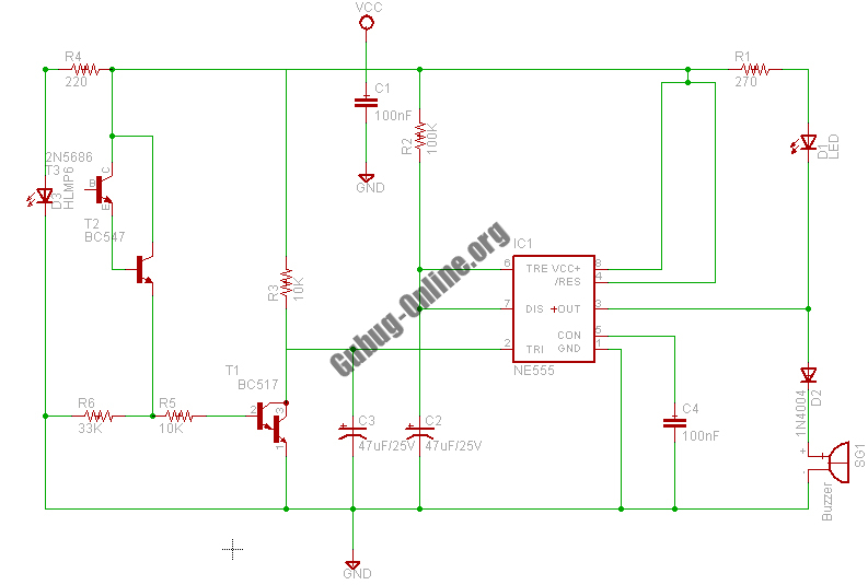
Description: This design circuit project involves a clear glass sensor circuit intended for experimental or hobbyist applications. The concept is straightforward and relies on a homemade sensor unit that includes one high-efficiency ultra-bright red LED (D1) and a standard phototransistor.
The clear glass sensor circuit operates on the principle of light detection and reflection. The ultra-bright red LED (D1) emits light, which is directed towards the glass surface. When an object approaches the sensor, the light emitted by the LED reflects off the glass and returns to the sensor unit. The phototransistor, which is sensitive to the wavelength of the emitted light, detects this reflected light.
In the schematic, the LED (D1) is connected in series with a current-limiting resistor to ensure that it operates within its specified current ratings. This resistor prevents excessive current from flowing through the LED, which could lead to overheating and failure. The phototransistor is connected in a configuration that allows it to act as a switch. When the reflected light reaches a certain intensity, the phototransistor turns on, allowing current to flow through its collector-emitter path.
The output from the phototransistor can be further processed or used to trigger other components in a circuit. For example, it could activate a relay to turn on a light or sound an alarm when an object is detected near the glass. Additional components, such as capacitors and diodes, may be included in the circuit to filter noise and protect against voltage spikes.
This clear glass sensor circuit is particularly useful in applications such as automatic doors, security systems, or interactive displays where proximity detection is required. The simplicity of the design makes it an excellent choice for educational purposes, allowing hobbyists to learn about basic electronic principles while experimenting with sensor technology.This is a design circuit project for a clear glass sensor circuit can be used for experiment/hobby purposes. The concept is very simple and is based on a home-made sensor unit comprising one high efficiency ultra bright red LED (D1) and a standard ph ..
The clear glass sensor circuit operates on the principle of light detection and reflection. The ultra-bright red LED (D1) emits light, which is directed towards the glass surface. When an object approaches the sensor, the light emitted by the LED reflects off the glass and returns to the sensor unit. The phototransistor, which is sensitive to the wavelength of the emitted light, detects this reflected light.
In the schematic, the LED (D1) is connected in series with a current-limiting resistor to ensure that it operates within its specified current ratings. This resistor prevents excessive current from flowing through the LED, which could lead to overheating and failure. The phototransistor is connected in a configuration that allows it to act as a switch. When the reflected light reaches a certain intensity, the phototransistor turns on, allowing current to flow through its collector-emitter path.
The output from the phototransistor can be further processed or used to trigger other components in a circuit. For example, it could activate a relay to turn on a light or sound an alarm when an object is detected near the glass. Additional components, such as capacitors and diodes, may be included in the circuit to filter noise and protect against voltage spikes.
This clear glass sensor circuit is particularly useful in applications such as automatic doors, security systems, or interactive displays where proximity detection is required. The simplicity of the design makes it an excellent choice for educational purposes, allowing hobbyists to learn about basic electronic principles while experimenting with sensor technology.This is a design circuit project for a clear glass sensor circuit can be used for experiment/hobby purposes. The concept is very simple and is based on a home-made sensor unit comprising one high efficiency ultra bright red LED (D1) and a standard ph ..
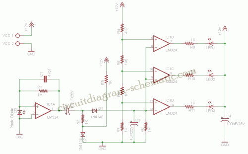
Simple Car Parking Sensor circuit
The car parking sensor circuit utilizes a photodiode as the distance sensor. It measures the distance between adjacent sensors.
The car parking sensor circuit employs photodiodes to detect the proximity of obstacles, enhancing parking safety and convenience. Photodiodes are semiconductor devices...
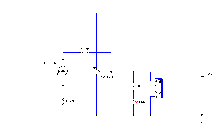
transceiver-circuits
While developing an infrared (IR) extender circuit, a method was needed to measure the relative intensities of different infrared light sources. This circuit utilizes an SFH2030 photodiode as the infrared sensor. A CA3140 MOSFET operational amplifier is employed in differential...
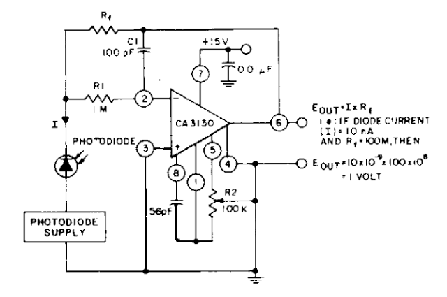
Photodiode current-to-voltage converter
The photodiode current-to-voltage converter circuit employs three CA3130 BiMOS operational amplifiers, designed for applications that require sensitivity to sub-picoampere input currents. This circuit generates a ground-referenced output voltage that is directly proportional to the input current flowing through the photodiode.
The...
Improved Photodiode Pre-Amp Uses Current-Feedback Amplifier
This design concept addresses a major challenge associated with the use of photodiodes in high-speed applications such as barcode scanners, CD-ROMs, and DVDs, specifically the high output capacitance of the diode. The critical component in the circuit is the Analog...
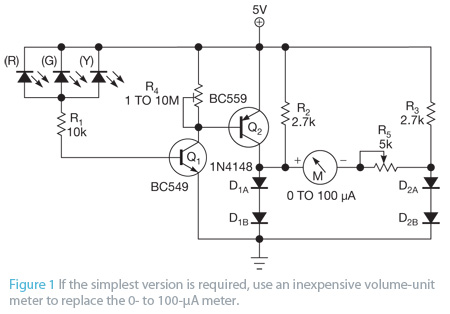
Photo Meter Assesses Ambient Light Schematic
Most PN-junction diodes can be utilized as photodiodes. Although they are not specifically optimized for this purpose, they are functional. When reverse biased, a diode generates a small photovoltaic output that increases with light intensity. Light Emitting Diodes (LEDs) are...
Photodiode-amplifier
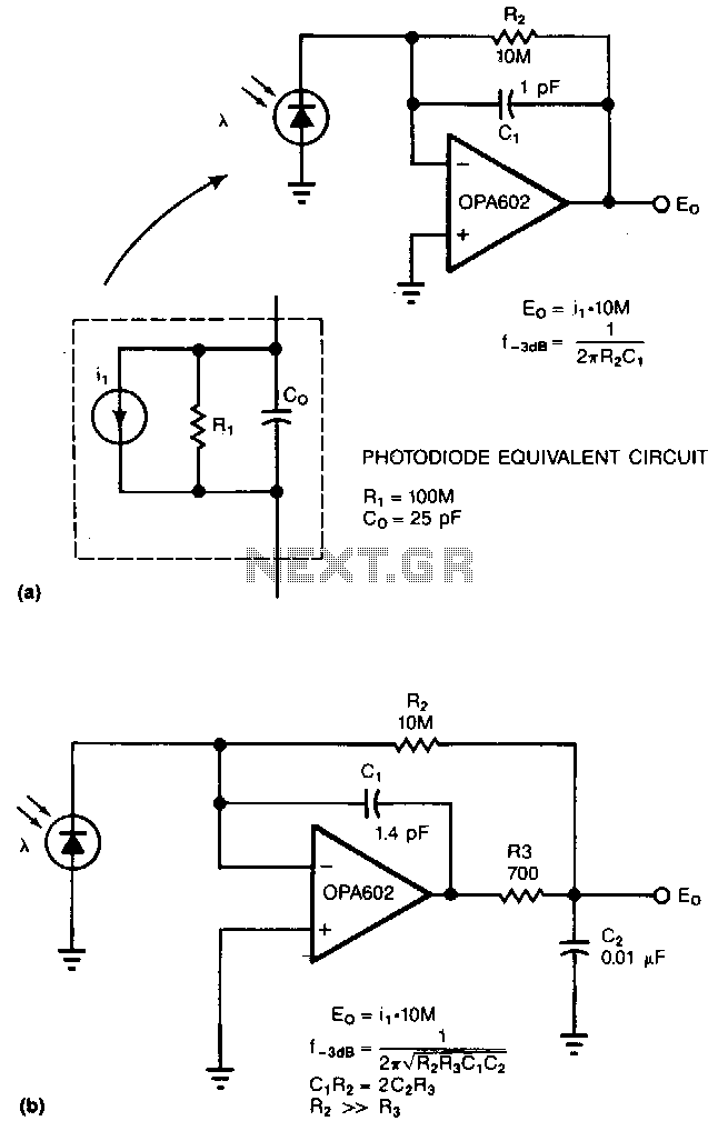
Adding two passive components to a standard photodiode amplifier reduces noise. Without the modification, the shunt capacitance of the photodiode reacting with the relatively large feedback resistor of the transimpedance (current-to-voltage) amplifier creates excessive noise gain. The improved circuit adds...
Photodiode-source-follower
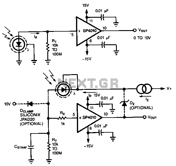
A common method of transforming the output current of a photodiode into a voltage signal involves paralleling the photodiode with a high-value load resistor, which results in a nonlinear response. Additionally, the combination of the load's transresistance, Rr, and the...
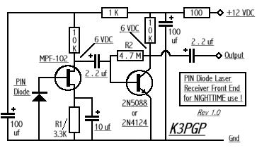
Modulated Light DX
Which type of modulated light receiver should be used? A photodiode directly connected to a high-gain, high-impedance amplifier; a photodiode connected to a current amplifier; a back-biased photodiode; FET input or bipolar IC or discrete components? How can noise be...
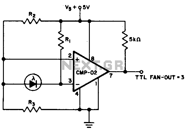
Precision photodiode level detector
The output state changes at a photodiode current of 0 µA. For R1 = 2 MΩ, R2 = R3 = 5 MΩ.
The described circuit likely involves a photodiode used in conjunction with resistors R1, R2, and R3 to create a...