


Connecting Infrared Thermometer MLX90614
#MLX90614
#infrared thermometer
#temperature sensor
#I2C
#PWM
#non-contact
#movement detection
#presence detection
#SMBus
#TWI
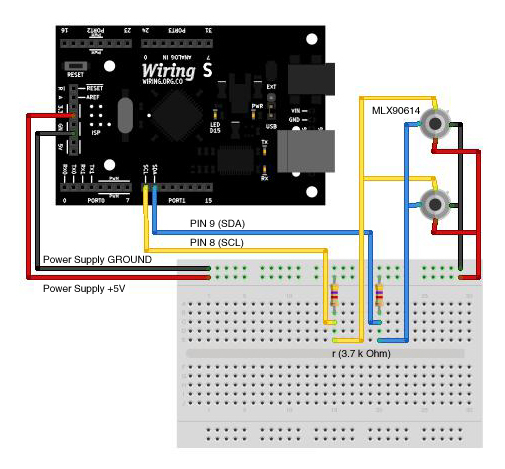
Description: The MLX90614 is an infrared thermometer that allows for non-contact temperature measurement, providing average temperature readings for objects within its view range. Besides its primary function of measuring temperature, it can also be utilized for motion or presence detection. This sensor can be interfaced in two ways: via PWM communication or SMBus (TWI or I²C) communication. The latter was chosen due to its advantages, including the ability to connect over 127 devices using only two wiring pins and improved resolution readings for the MLX90614. However, the standard Wire library for I²C devices is incompatible with the MLX90614 due to its lack of support for the repeated start function. Instead, the I²Cmaster library, modified for compatibility, is used. This library must be downloaded and installed. The setup involves connecting the MLX90614 to the TWI pins on the Wiring board, using specific pin assignments. The provided code demonstrates how to read temperature data from the MLX90614 and output the results in both Celsius and Fahrenheit.
The MLX90614 infrared thermometer operates through the principle of non-contact temperature measurement, utilizing infrared radiation emitted by objects. This sensor is particularly advantageous in applications where traditional thermometers may not be feasible, such as measuring the temperature of moving objects or in hazardous environments.
To interface with the MLX90614, the preferred method is through I²C communication, which allows for a simplified wiring setup and the ability to connect multiple devices on the same bus. The I²C protocol operates with two wires: Serial Data Line (SDA) and Serial Clock Line (SCL). For the Wiring v1 board, the I²C pins are designated as 0 for SCL and 1 for SDA, while for the Wiring S board, they are 8 for SCL and 9 for SDA.
The I²Cmaster library is essential for effective communication with the MLX90614. This library is tailored to support the specific requirements of the MLX90614, particularly addressing the repeated start condition that the standard Wire library does not accommodate. Upon installation of the I²Cmaster library, the sensor can be initialized and configured to read temperature data.
The provided code initializes the serial communication at a baud rate of 9600 and sets up the I²C bus. It includes a loop that continuously reads the temperature from the MLX90614, converts the readings from Celsius to Fahrenheit, and outputs both values to the serial monitor. The temperature reading is processed by gathering high and low byte data from the sensor, applying necessary conversions, and adjusting for resolution.
Overall, the MLX90614 sensor, when interfaced correctly through the I²C protocol using the I²Cmaster library, provides accurate and reliable temperature readings, making it a valuable tool for various applications in electronics and automation.MLX90614 is a very useful infrared thermometer (no contact needed) that gives you the average temperature reading of all objects in the view range. In addition to it`s principal temperature reading function, it can be used for movement or even presence detection.
There are two ways of interfacing this sensor, through PWM communication or SMBus (TWI or I ²C) communication. I wasn`t able to get the first one working, so tried SMBus I ²C that is not easier to code but gives you some advantages over PWM. Through I ²C you can connect over 127 devices using just two Wiring pins and also, in this specific sensor (MLX90614) you get better resolution readings.
Wiring comes with a special library for interfacing I ²C devices (wire library) but unfortunately this library is not compatible with MLX90614 because it doesn`t support the use of the repeated start function (if you want to read further about this issue check this link ). So, we are going to use the I ²Cmaster library that has been modified by the guys at bildr. blog for working properly with the Wiring board. The first thing that has to be done is to download and instal the the I ²Cmaster library. As I said before, were using a version modified by the guys at bildr. blog. Once you have the library installed, you can use the following setup diagram and code for reading temperature from one MLX90614 connected to the TWI pins (on the Wiring v1 board 0 (SCL) and 1 (SDA) and on Wiring S board 8 (SCL) and 9 (SDA).
Both (diagram and code) are based on the Is it hot Arduino + MLX90614 IR Thermometer bildr. blog post. /* * Infrared Thermometer MLX90614 * by Jaime Patarroyo * based on `Is it hot Arduino + MLX90614 IR Thermometer` by bildr. blog * * Returns the temperature in Celcius and Fahrenheit from a MLX90614 * Infrared Thermometer, connected to the TWI/I ²C pins (on the Wiring v1 * board 0 (SCL) and 1 (SDA) and on Wiring S board 8 (SCL) and 9 (SDA).
*/ #include int deviceAddress = 0x5A<<1; // From MLX906114 datasheet`s, 0x5A is // the default address for I ²C communication. // Shift the address 1 bit right, the // I ²Cmaster library only needs the 7 most // significant bits for the address. float celcius = 0; // Variable to hold temperature in Celcius. float fahrenheit = 0; // Variable to hold temperature in Fahrenheit. void setup() { Serial. begin(9600); // Start serial communication at 9600bps. i2c_init(); // Initialise the i2c bus. PORTC = (1 << PORTC4) | (1 << PORTC5); // Enable pullups. } void loop() { celcius = temperatureCelcius(deviceAddress); // Read`s data from MLX90614 // with the given address, // transform`s it into // temperature in Celcius and // store`s it in the Celcius // variable.
fahrenheit = (celcius*1. 8) + 32; // Converts celcius into Fahrenheit // and stores in Fahrenheit variable. Serial. print("Celcius: "); // Prints both readings in the Serial Serial. println(celcius); // port. Serial. print("Fahrenheit: "); Serial. println(fahrenheit); delay(1000); // Wait a second before printing again. } float temperatureCelcius(int address) { int dev = address; int data_low = 0; int data_high = 0; int pec = 0; // Write i2c_start_wait(dev+I2C_WRITE); i2c_write(0x07); // Read i2c_rep_start(dev+I2C_READ); data_low = i2c_readAck(); // Read 1 byte and then send ack. data_high = i2c_readAck(); // Read 1 byte and then send ack. pec = i2c_readNak(); i2c_stop(); // This converts high and low bytes together and processes temperature, // MSB is a error bit and is ignored for temps.
double tempFactor = 0. 02; // 0. 02 degrees per LSB (measurement // resolution of the MLX90614). double tempData = 0x0000; // Zero out the data int frac; // Data past the decimal point // This masks off the error bit of the high byte, then moves it left // 8 bits and adds the low byte. tempData = (double)(data_high & 0x007F) << 8) + data_low); tempData = (tempData * tempFactor)-0. 01; float celcius = tempData - 273. 15; // R
The MLX90614 infrared thermometer operates through the principle of non-contact temperature measurement, utilizing infrared radiation emitted by objects. This sensor is particularly advantageous in applications where traditional thermometers may not be feasible, such as measuring the temperature of moving objects or in hazardous environments.
To interface with the MLX90614, the preferred method is through I²C communication, which allows for a simplified wiring setup and the ability to connect multiple devices on the same bus. The I²C protocol operates with two wires: Serial Data Line (SDA) and Serial Clock Line (SCL). For the Wiring v1 board, the I²C pins are designated as 0 for SCL and 1 for SDA, while for the Wiring S board, they are 8 for SCL and 9 for SDA.
The I²Cmaster library is essential for effective communication with the MLX90614. This library is tailored to support the specific requirements of the MLX90614, particularly addressing the repeated start condition that the standard Wire library does not accommodate. Upon installation of the I²Cmaster library, the sensor can be initialized and configured to read temperature data.
The provided code initializes the serial communication at a baud rate of 9600 and sets up the I²C bus. It includes a loop that continuously reads the temperature from the MLX90614, converts the readings from Celsius to Fahrenheit, and outputs both values to the serial monitor. The temperature reading is processed by gathering high and low byte data from the sensor, applying necessary conversions, and adjusting for resolution.
Overall, the MLX90614 sensor, when interfaced correctly through the I²C protocol using the I²Cmaster library, provides accurate and reliable temperature readings, making it a valuable tool for various applications in electronics and automation.MLX90614 is a very useful infrared thermometer (no contact needed) that gives you the average temperature reading of all objects in the view range. In addition to it`s principal temperature reading function, it can be used for movement or even presence detection.
There are two ways of interfacing this sensor, through PWM communication or SMBus (TWI or I ²C) communication. I wasn`t able to get the first one working, so tried SMBus I ²C that is not easier to code but gives you some advantages over PWM. Through I ²C you can connect over 127 devices using just two Wiring pins and also, in this specific sensor (MLX90614) you get better resolution readings.
Wiring comes with a special library for interfacing I ²C devices (wire library) but unfortunately this library is not compatible with MLX90614 because it doesn`t support the use of the repeated start function (if you want to read further about this issue check this link ). So, we are going to use the I ²Cmaster library that has been modified by the guys at bildr. blog for working properly with the Wiring board. The first thing that has to be done is to download and instal the the I ²Cmaster library. As I said before, were using a version modified by the guys at bildr. blog. Once you have the library installed, you can use the following setup diagram and code for reading temperature from one MLX90614 connected to the TWI pins (on the Wiring v1 board 0 (SCL) and 1 (SDA) and on Wiring S board 8 (SCL) and 9 (SDA).
Both (diagram and code) are based on the Is it hot Arduino + MLX90614 IR Thermometer bildr. blog post. /* * Infrared Thermometer MLX90614 * by Jaime Patarroyo * based on `Is it hot Arduino + MLX90614 IR Thermometer` by bildr. blog * * Returns the temperature in Celcius and Fahrenheit from a MLX90614 * Infrared Thermometer, connected to the TWI/I ²C pins (on the Wiring v1 * board 0 (SCL) and 1 (SDA) and on Wiring S board 8 (SCL) and 9 (SDA).
*/ #include
fahrenheit = (celcius*1. 8) + 32; // Converts celcius into Fahrenheit // and stores in Fahrenheit variable. Serial. print("Celcius: "); // Prints both readings in the Serial Serial. println(celcius); // port. Serial. print("Fahrenheit: "); Serial. println(fahrenheit); delay(1000); // Wait a second before printing again. } float temperatureCelcius(int address) { int dev = address; int data_low = 0; int data_high = 0; int pec = 0; // Write i2c_start_wait(dev+I2C_WRITE); i2c_write(0x07); // Read i2c_rep_start(dev+I2C_READ); data_low = i2c_readAck(); // Read 1 byte and then send ack. data_high = i2c_readAck(); // Read 1 byte and then send ack. pec = i2c_readNak(); i2c_stop(); // This converts high and low bytes together and processes temperature, // MSB is a error bit and is ignored for temps.
double tempFactor = 0. 02; // 0. 02 degrees per LSB (measurement // resolution of the MLX90614). double tempData = 0x0000; // Zero out the data int frac; // Data past the decimal point // This masks off the error bit of the high byte, then moves it left // 8 bits and adds the low byte. tempData = (double)(data_high & 0x007F) << 8) + data_low); tempData = (tempData * tempFactor)-0. 01; float celcius = tempData - 273. 15; // R
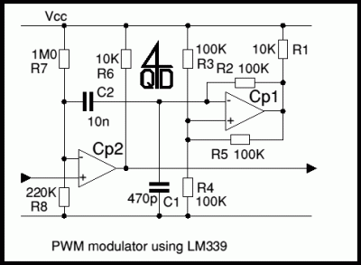
Pulse Width Modulators using LM339
The first example utilizes a standard op-amp oscillator circuit to produce a triangular waveform, which is then level-shifted and supplied to a comparator (e.g., LM339) to generate a PWM waveform. It is common for users to prefer using two comparators...
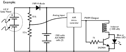
Microcontroller driving a Joule Thief circuit
This example demonstrates the PWM (pulse-width modulation) output of a microcontroller controlling a Joule Thief style voltage booster to power a white LED.
The circuit described utilizes a microcontroller to generate a PWM signal, which is an effective method for controlling...
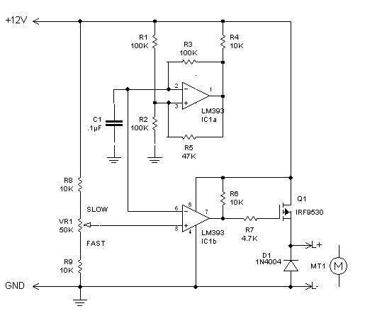
PWM circuit
The inquiry pertains to identifying the component within the circuit that regulates the minimum RPM achievable. The current operational range of the motor is between 1400 and 3700 RPM, and there is an interest in modifying the circuit to lower...
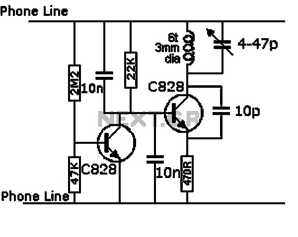
thermometer circuit using lm335
The circuit illustrated below represents a simple thermometer circuit based on the LM335 temperature sensor. This circuit comprises two main components: the LM335 sensor and its adjustment circuitry. The output from the LM335 generates a voltage of 10 millivolts per...
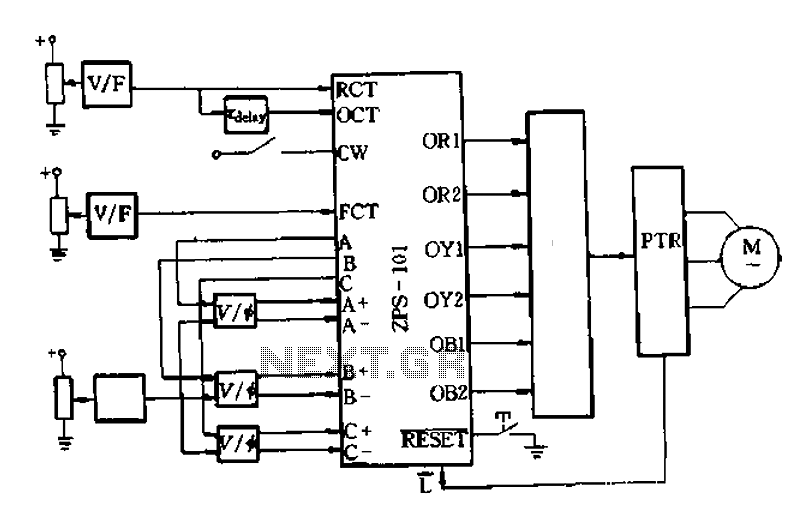
Analog PWM connection with FIG zps-101 interface
An AC-DC-AC circuit utilizes a power transistor as a switching device with analog control, as recommended in the wiring diagram of Figure 6-10. This circuit generates a voltage-controlled oscillator (VCO) using OCT and FCT, with RCT available for OCT delay....

Intelligent thermostat temperature sensor LM75 circuit diagram consisting
The circuit features simple smart temperature sensors utilizing an I2C bus interface, designed as a thermostat controller circuit. It employs the LM75 temperature sensor connected to a 2N3904 transistor, which drives a relay coil. The relay operates based on the...
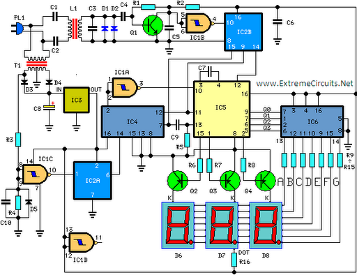
Digital Remote Thermometer
This circuit is designed for precise measurement of temperature in degrees Celsius. It features a transmitter section that converts the output voltage from a temperature sensor, which is proportional to the temperature being measured, into frequency. The resulting frequency bursts...
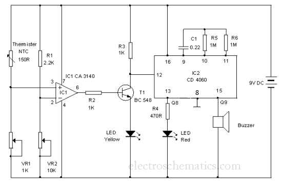
Cold Sensor
The resistance decreases when the temperature in its vicinity increases by one degree or more. Component: LED, Buzzer, Transistor, Capacitor, etc.
The described component exhibits a negative temperature coefficient, which means that its resistance decreases as ambient temperature increases. This behavior...
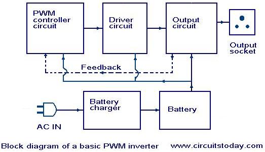
Introduction to PWM Inverters
Nowadays, most inverters available in the market utilize Pulse Width Modulation (PWM) technology. Inverters based on PWM technology exhibit superior performance in several aspects compared to those designed using conventional methods. These PWM inverters typically employ MOSFETs in the output...