


Digitizer
#digitizer
#level transducer
#ac bridge excitation
#multivibrator
#transducer
#resistance
#gravity sensor
#bridge circuit
#LT1009
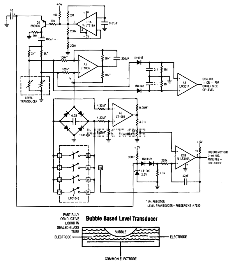
Description: When the tube is aligned with gravity, the bubble is positioned at the center of the tube, resulting in identical electrode resistances to the common reference. As the tube deviates from this level position, the resistances vary proportionally. This type of transducer requires an alternating current (AC) waveform for excitation to prevent damage to the partially conductive liquid within the tube. The level transducer is designed with a pair of 2 kΩ resistors configured to form a bridge circuit. The necessary AC bridge excitation is generated by circuit ClA, which is set up as a multivibrator. The output from Cl biases transistor Q1, which switches the LT1009's 2.5 V potential through a 100 µF capacitor, providing the AC drive for the bridge.
The differential output AC signal from the bridge is converted into a current by amplifier A1, functioning as a Howland current pump. This current, which reverses polarity as the bridge drive polarity changes, is rectified by a diode bridge, resulting in unipolar charging of a 0.03 µF capacitor. Amplifier A2, configured with a differential gain of 2, monitors the voltage across the capacitor and presents its single-ended output to circuit ClB. Once the voltage across the 0.03 µF capacitor reaches a sufficient level, the output from ClB becomes high, activating the paralleled sections of the LTC1043 switch to discharge the capacitor. A 47 pF capacitor provides adequate AC feedback around ClB, enabling a complete reset of the capacitor. When the AC feedback ceases, ClB's output diminishes, and the LTC1043 switch turns off. The 0.03 µF capacitor then resumes constant current charging, and the entire cycle restarts. The frequency of this oscillation is dictated by the magnitude of the constant current supplied to the bridge-capacitor configuration, which is influenced by the offset of the transducer bridge, directly related to the level of the tube.
In this circuit, the design employs a bridge configuration to measure the liquid level accurately. The resistors in the bridge are critical for balancing the circuit, ensuring that any deviation from the level results in a measurable change in resistance. The use of an AC excitation signal is essential to mitigate the effects of electrolysis that could occur with direct current, which could harm the conductive liquid.
The Howland current pump is a pivotal component in converting the AC signal from the bridge into a usable current, allowing for effective signal processing. The diode bridge rectifies the alternating current, converting it into a unidirectional flow that charges the capacitor, which acts as both an energy storage element and a key variable in the feedback loop.
Amplifier A2's differential gain is crucial for amplifying the voltage across the capacitor, ensuring that the output signal to ClB is robust enough to trigger the LTC1043 switch reliably. The feedback mechanism provided by the 47 pF capacitor is essential for maintaining the stability of the circuit during operation, allowing for a quick reset after each cycle.
This entire configuration results in a precise measurement system that can continuously monitor the liquid level and respond dynamically to changes, making it suitable for various applications where liquid levels need to be controlled or monitored accurately. The design emphasizes reliability and efficiency, ensuring that the system can operate effectively over extended periods.If the tube is level with respect to gravity, the bubble resides in the tube"s center and the electrode resistances to common are identical. As the tube shifts away from level, the resistances increase and decrease proportionally. Transducers of this type must be excited with an ac waveform to avoid damage to the partially conductive liquid inside the tube.
The level transducer is configured with a pair of 2-KO resistors to form a bridge. The required ac bridge excitation is developed at ClA, configured as a multivibrator. Cl biases Ql, which switches the LT1009"s 2.5-V potential through the 100-~
Thus, the 0.03ILF capacitor receives unipolar charge. A2, running at a differential gain of 2, senses the voltage across the capacitor and presents its single-ended output to ClB. When the voltage across the 0.03-~
When the ac feedback ceases, ClB"s output decreases and the LTC1043 switch goes off. The 0.03-~
Related Circuits
The differential output AC signal from the bridge is converted into a current by amplifier A1, functioning as a Howland current pump. This current, which reverses polarity as the bridge drive polarity changes, is rectified by a diode bridge, resulting in unipolar charging of a 0.03 µF capacitor. Amplifier A2, configured with a differential gain of 2, monitors the voltage across the capacitor and presents its single-ended output to circuit ClB. Once the voltage across the 0.03 µF capacitor reaches a sufficient level, the output from ClB becomes high, activating the paralleled sections of the LTC1043 switch to discharge the capacitor. A 47 pF capacitor provides adequate AC feedback around ClB, enabling a complete reset of the capacitor. When the AC feedback ceases, ClB's output diminishes, and the LTC1043 switch turns off. The 0.03 µF capacitor then resumes constant current charging, and the entire cycle restarts. The frequency of this oscillation is dictated by the magnitude of the constant current supplied to the bridge-capacitor configuration, which is influenced by the offset of the transducer bridge, directly related to the level of the tube.
In this circuit, the design employs a bridge configuration to measure the liquid level accurately. The resistors in the bridge are critical for balancing the circuit, ensuring that any deviation from the level results in a measurable change in resistance. The use of an AC excitation signal is essential to mitigate the effects of electrolysis that could occur with direct current, which could harm the conductive liquid.
The Howland current pump is a pivotal component in converting the AC signal from the bridge into a usable current, allowing for effective signal processing. The diode bridge rectifies the alternating current, converting it into a unidirectional flow that charges the capacitor, which acts as both an energy storage element and a key variable in the feedback loop.
Amplifier A2's differential gain is crucial for amplifying the voltage across the capacitor, ensuring that the output signal to ClB is robust enough to trigger the LTC1043 switch reliably. The feedback mechanism provided by the 47 pF capacitor is essential for maintaining the stability of the circuit during operation, allowing for a quick reset after each cycle.
This entire configuration results in a precise measurement system that can continuously monitor the liquid level and respond dynamically to changes, making it suitable for various applications where liquid levels need to be controlled or monitored accurately. The design emphasizes reliability and efficiency, ensuring that the system can operate effectively over extended periods.If the tube is level with respect to gravity, the bubble resides in the tube"s center and the electrode resistances to common are identical. As the tube shifts away from level, the resistances increase and decrease proportionally. Transducers of this type must be excited with an ac waveform to avoid damage to the partially conductive liquid inside the tube.
The level transducer is configured with a pair of 2-KO resistors to form a bridge. The required ac bridge excitation is developed at ClA, configured as a multivibrator. Cl biases Ql, which switches the LT1009"s 2.5-V potential through the 100-~
Thus, the 0.03ILF capacitor receives unipolar charge. A2, running at a differential gain of 2, senses the voltage across the capacitor and presents its single-ended output to ClB. When the voltage across the 0.03-~
When the ac feedback ceases, ClB"s output decreases and the LTC1043 switch goes off. The 0.03-~
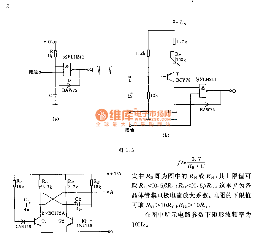
Astable flip-flop multivibrator circuit
The circuit consists of two components whose parameters and models are designed to simultaneously generate a rectangular wave with a duty cycle of 1:1. The frequency is defined by the equation f = 0.7/(RB * C), where RB refers to...
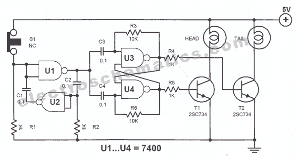
Electronic Head or Tail Circuit
The principle utilized in this electronic head or tail circuit is straightforward: a multivibrator controls a flip-flop. The multivibrator oscillates as long as the button S1 is pressed, while the flip-flop toggles on and off at a frequency of several...

Transducer amplifier
This circuit features a high-input-impedance AC resistance of 880 kΩ and a gain of 10, utilizing an operational amplifier for a piezoelectric transducer.
The described circuit is designed to interface with a piezoelectric transducer, which generates an AC voltage in response...

Irregular Flasher
Two multivibrators with different frequencies can be constructed using the NAND gates of a 4011 integrated circuit (IC). When the output of IC1, pin B is positive in relation to pin C, LED D1 illuminates. As the states of IC1,...
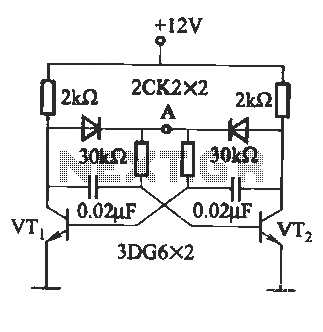
Improved multivibrator circuit
The circuit illustrated in Figure (A) consists of resistors R1 and R2 with values ranging from 15 to 18 kΩ, and capacitors C1 and C2 with capacitance values between 0.01 µF and 10 µF. Figure (B) depicts the oscillation frequency,...
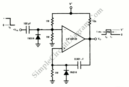
One-Shot Multivibrator
A one-shot multivibrator generates a fixed-width pulse at the output when triggered by an input signal. This fixed-width output remains consistent, regardless of the input signal duration.
The one-shot multivibrator, also known as a monostable multivibrator, is a crucial component in...
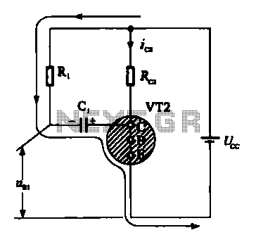
Multivibrator oscillation circuit
When VRI is off, 0 [2 is activated, allowing current to flow through RJ and Ci. When VT1 conducts, charging of C1 begins, causing it to discharge. This results in an inverting charge on C1, making the voltage positive, which...
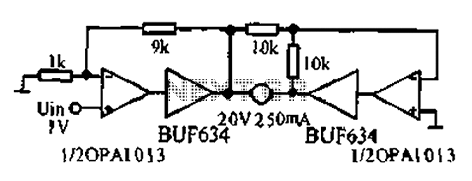
Bridge motor drive circuit
A bridge motor drive circuit is illustrated, featuring a driving stage composed of four transistors. The control circuit includes four terminals labeled A, B, C, and D, which facilitate the control of forward or reverse motor rotation. The control mode...
Improved multivibrator circuit
The circuit illustrated in Figure (A) consists of resistors R1 and R2 with values ranging from 15 to 18 kΩ, and capacitors C1 and C2 with capacitance values between 0.01 µF and 10 µF. Figure (B) depicts the oscillation frequency,...