


DS1820 thermometer circuit
#DS18S20
#temperature sensor
#digital thermometer
#voltage doubler
#LCD panel
#precision measurement
#thermocontractile tube
#coaxial cable
#SCRATCHPAD
#0.5°C precision
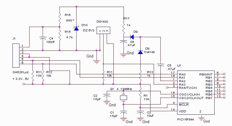
Description: The DS18S20 digital thermometer offers a precision of 0.5 °C, with the SCRATCHPAD being read every 800 ms. Capacitors C5 and C6, along with diodes D8 and D9, form a voltage doubler to power the LCD panel. The DS18S20 temperature sensor is encased in a heat-shrink tubing. A coaxial stereo cable, measuring only 1 meter in length, is selected for connections, making it suitable for most applications. The schematic includes an IIC LCD driver (PCF2103) with connections for RA0, RA1 for IIC SCLK and SDATA, and RA2, RA3 for PWM and DS1820 data I/O. It utilizes an internal clock with a standard crystal operating at 4.194 MHz.
The code is written for the PIC16F84 microcontroller, with specific configurations for code protection, power-on timer, watchdog timer, and crystal oscillator settings. The initialization process involves setting up the LCD and configuring various parameters for display, including instruction registers for multiple command bytes and character generation.
The LCD initialization commands include setting the extended instruction set, display configuration, and cursor movement direction. The data subroutine handles character display on the LCD, while the temperature reading process involves sending commands to the DS18S20 sensor to initiate temperature conversion and read the results.
The schematic also includes routines for handling data flow and control signals, ensuring accurate temperature readings and proper LCD operation.
The DS18S20 digital thermometer circuit is designed to provide reliable temperature measurements with a precision of 0.5 °C. It is equipped with a SCRATCHPAD memory that enables temperature data to be read every 800 ms, facilitating timely updates on the LCD display. The inclusion of capacitors C5 and C6, along with diodes D8 and D9, creates a voltage doubler circuit that supplies the necessary power to the LCD panel, ensuring consistent performance.
The DS18S20 temperature sensor is protected within a heat-shrink tubing, providing durability and resistance to environmental factors. A coaxial stereo cable, measuring 1 meter, is used for connections, making it ideal for a wide range of applications without excessive cable length.
The schematic features an IIC LCD driver (PCF2103), which interfaces with the microcontroller through pins RA0 and RA1 for the IIC serial clock and data lines. Additionally, RA2 and RA3 are utilized for PWM signals and data input/output from the DS1820 temperature sensor. The internal clock of the system is based on a standard crystal oscillator, operating at 4.194 MHz, ensuring precise timing for the operations of the microcontroller.
The firmware is developed for the PIC16F84 microcontroller, incorporating various configuration settings such as disabling code protection, enabling the power-on timer, and turning off the watchdog timer. The initialization sequence includes setting up the LCD with appropriate commands to configure display settings, cursor behavior, and data handling.
The LCD initialization commands are meticulously structured to ensure that the display operates correctly, with specific instructions for setting the extended instruction set, display configuration, and cursor movement. The data subroutine is responsible for displaying the temperature readings on the LCD, while the temperature measurement routine communicates with the DS18S20 sensor to initiate readings and retrieve temperature data.
Overall, the DS18S20 digital thermometer circuit is designed for efficient and accurate temperature monitoring, with a robust interface for data display and control. The combination of precise components and well-structured firmware enables reliable operation in various applications.This DS18S20 digital thermometer provides a precision of 0. 5 °C and SCRATCHPAD it`s read at every 800ms. Capacitors C5, C6 and diodes D8, D8 makes a voltage doublers which power the lcd panel. The DS18S20 temperature sensor it`s wrapped in a thermo contractil tube. For connection cable I chose a type used in audio (coaxial stereo) that is only 1 m long, perfect for most applications. ;=lcd digital thermometer with ds18s20 Version 2. 1=14/11/03= ; iic lcd driver: PCF2103 ; ra0, ra1 iic sclock, sdata ; ra2, ra3 pwm, ds1820 data I/O ; internal clock ; standard crystal 4. 194 MHz XT -. 95us pe instructiune ; ;- list p=16f84;f=inhx8m #INCLUDE P16F84. INC _CP_OFF equ H`3FFF` ;code protect off _PwRTE_ON equ H`3FFF` ;Power on timer on _wDT_OFF equ H`3FFB` ;watch dog timer off _XT_OSC equ H`3FFD` ;crystal oscillator _CONFIG _CP_OFF & _PwRTE_ON & _wDT_OFF & _XT_OSC ;- ; cpu init count1 equ 0C count2 equ 0D count3 equ 0E transo equ 0F ratb equ 10 dig1 equ 11 dig2 equ 12 dig3 equ 13 semn equ 14 #DEFINE sclk PORTA, 0 #DEFINE sdta PORTA, 1 #DEFINE osc PORTA, 2 #DEFINE grad PORTA, 3 ;- ;- ; cpu init org 0x00 goto init org 0x04 ; ;- init call usaex call usbex movlw 0x00 movwf PORTA movwf PORTB clrf semn ;* ;* ;* Lcd init commands * ;* lcd_ini call iict ; i2c start movlw 0x74 ; device write address (75h for read) call act ; i2c send subroutine movlw 0x00 ; Co, RS=0, set instruction register for multiple next command bytes call act movlw 0x31 ; extended instruction set call act movlw 0x02 ; set screen configuration left to right call act movlw 0x05 ; set display configuration call act movlw 0x08 ; set icon mode, full mode, icon blink disable call act movlw 0x30 ; normal instruction set call act movlw 0x0C ; set display on call act movlw 0x06 ; set cursor move direction call act movlw 0x02 ; set DDRAM address 0 in address counter call act call iicp ; i2c stop ;* ;* Lcd icon sets off * ;* call iict movlw 0x74 call act movlw 0x80 ; Co=1, RS=0 just one next command byte call act movlw 0x4C ; set CGRAM for icons call act movlw 0x40 ; Co=0, RS=1, set instruction register for multiple next data bytes call act movlw 0x00 ; erase icons sequence call act movlw 0x18 call act movlw 0x00 call act movlw 0x00 call act movlw 0x00 call act movlw 0x00 call act movlw 0x00 call act movlw 0x00 call act movlw 0x00 call act movlw 0x00 call act movlw 0x00 call act movlw 0x00 call act movlw 0x0F call act movlw 0x10 call act call iicp ; i2c stop ;* ;* Lcd cursor subroutine * ;* call iict movlw 0x74 call act movlw 0x00 call act movlw 0x30 call act movlw 0x01 ; clears entire display and sets DDRAM address to 0 in address counter call act movlw 0x0C ; display on, cursor off, cursor blink off call act call iicp ;* ;* Lcd data subroutine * ;* nou call iict movlw 0x74 call act movlw 0x80 ; Co=1, RS=0 just one next command byte call act movlw 0x8C ; set CGRAM for characters call act movlw 0x40 ; Co=0, RS=1, set instruction register for multiple next data bytes call act movlw 0xD4 ; T call act movlw 0xE5 ; e call act movlw 0xED ; m call act movlw 0xF0 ; p call act movlw 0xBA ; : call act movlw 0xAB ; btfsc semn, 0 addlw 0x02 call act scrie call rset movlw 0xCC ;skip rom call schtx movlw 0x44 ;convert call schtx call halta call rset movlw 0xCC ;skip rom call schtx movlw 0xBE ;read scratchpad call schtx call schrx call mux movf dig2, 0 addlw 0xB0 call act movf dig1, 0 addlw 0xB0 call act movlw 0xAC call act movf dig3, 0 addlw 0xB0 call act movlw 0x20 ; call act movlw 0xC3 ; call act call iicp goto nou ;* rset bcf grad call halte ; 510 us bsf grad call usain call haltd ; 61 us btfsc grad bsf PORTB, 0 btfss grad bcf PORTB, 0 call halte ; 510us call usaex retlw 00 ;* schtx movwf ratb ; movlw 0x08 movwf count3 ;* gbit btfsc ratb, 0 ; data reverse flow call unu btfss ratb, 0 call nul rrf ratb, F decfsz count3, F goto gbit retlw 00 ;* schrx movlw 0x08 movwf count3 samp rrf ratb, F bcf grad call usain call haltcc ; 11us bt
The code is written for the PIC16F84 microcontroller, with specific configurations for code protection, power-on timer, watchdog timer, and crystal oscillator settings. The initialization process involves setting up the LCD and configuring various parameters for display, including instruction registers for multiple command bytes and character generation.
The LCD initialization commands include setting the extended instruction set, display configuration, and cursor movement direction. The data subroutine handles character display on the LCD, while the temperature reading process involves sending commands to the DS18S20 sensor to initiate temperature conversion and read the results.
The schematic also includes routines for handling data flow and control signals, ensuring accurate temperature readings and proper LCD operation.
The DS18S20 digital thermometer circuit is designed to provide reliable temperature measurements with a precision of 0.5 °C. It is equipped with a SCRATCHPAD memory that enables temperature data to be read every 800 ms, facilitating timely updates on the LCD display. The inclusion of capacitors C5 and C6, along with diodes D8 and D9, creates a voltage doubler circuit that supplies the necessary power to the LCD panel, ensuring consistent performance.
The DS18S20 temperature sensor is protected within a heat-shrink tubing, providing durability and resistance to environmental factors. A coaxial stereo cable, measuring 1 meter, is used for connections, making it ideal for a wide range of applications without excessive cable length.
The schematic features an IIC LCD driver (PCF2103), which interfaces with the microcontroller through pins RA0 and RA1 for the IIC serial clock and data lines. Additionally, RA2 and RA3 are utilized for PWM signals and data input/output from the DS1820 temperature sensor. The internal clock of the system is based on a standard crystal oscillator, operating at 4.194 MHz, ensuring precise timing for the operations of the microcontroller.
The firmware is developed for the PIC16F84 microcontroller, incorporating various configuration settings such as disabling code protection, enabling the power-on timer, and turning off the watchdog timer. The initialization sequence includes setting up the LCD with appropriate commands to configure display settings, cursor behavior, and data handling.
The LCD initialization commands are meticulously structured to ensure that the display operates correctly, with specific instructions for setting the extended instruction set, display configuration, and cursor movement. The data subroutine is responsible for displaying the temperature readings on the LCD, while the temperature measurement routine communicates with the DS18S20 sensor to initiate readings and retrieve temperature data.
Overall, the DS18S20 digital thermometer circuit is designed for efficient and accurate temperature monitoring, with a robust interface for data display and control. The combination of precise components and well-structured firmware enables reliable operation in various applications.This DS18S20 digital thermometer provides a precision of 0. 5 °C and SCRATCHPAD it`s read at every 800ms. Capacitors C5, C6 and diodes D8, D8 makes a voltage doublers which power the lcd panel. The DS18S20 temperature sensor it`s wrapped in a thermo contractil tube. For connection cable I chose a type used in audio (coaxial stereo) that is only 1 m long, perfect for most applications. ;=lcd digital thermometer with ds18s20 Version 2. 1=14/11/03= ; iic lcd driver: PCF2103 ; ra0, ra1 iic sclock, sdata ; ra2, ra3 pwm, ds1820 data I/O ; internal clock ; standard crystal 4. 194 MHz XT -. 95us pe instructiune ; ;- list p=16f84;f=inhx8m #INCLUDE P16F84. INC _CP_OFF equ H`3FFF` ;code protect off _PwRTE_ON equ H`3FFF` ;Power on timer on _wDT_OFF equ H`3FFB` ;watch dog timer off _XT_OSC equ H`3FFD` ;crystal oscillator _CONFIG _CP_OFF & _PwRTE_ON & _wDT_OFF & _XT_OSC ;- ; cpu init count1 equ 0C count2 equ 0D count3 equ 0E transo equ 0F ratb equ 10 dig1 equ 11 dig2 equ 12 dig3 equ 13 semn equ 14 #DEFINE sclk PORTA, 0 #DEFINE sdta PORTA, 1 #DEFINE osc PORTA, 2 #DEFINE grad PORTA, 3 ;- ;- ; cpu init org 0x00 goto init org 0x04 ; ;- init call usaex call usbex movlw 0x00 movwf PORTA movwf PORTB clrf semn ;* ;* ;* Lcd init commands * ;* lcd_ini call iict ; i2c start movlw 0x74 ; device write address (75h for read) call act ; i2c send subroutine movlw 0x00 ; Co, RS=0, set instruction register for multiple next command bytes call act movlw 0x31 ; extended instruction set call act movlw 0x02 ; set screen configuration left to right call act movlw 0x05 ; set display configuration call act movlw 0x08 ; set icon mode, full mode, icon blink disable call act movlw 0x30 ; normal instruction set call act movlw 0x0C ; set display on call act movlw 0x06 ; set cursor move direction call act movlw 0x02 ; set DDRAM address 0 in address counter call act call iicp ; i2c stop ;* ;* Lcd icon sets off * ;* call iict movlw 0x74 call act movlw 0x80 ; Co=1, RS=0 just one next command byte call act movlw 0x4C ; set CGRAM for icons call act movlw 0x40 ; Co=0, RS=1, set instruction register for multiple next data bytes call act movlw 0x00 ; erase icons sequence call act movlw 0x18 call act movlw 0x00 call act movlw 0x00 call act movlw 0x00 call act movlw 0x00 call act movlw 0x00 call act movlw 0x00 call act movlw 0x00 call act movlw 0x00 call act movlw 0x00 call act movlw 0x00 call act movlw 0x0F call act movlw 0x10 call act call iicp ; i2c stop ;* ;* Lcd cursor subroutine * ;* call iict movlw 0x74 call act movlw 0x00 call act movlw 0x30 call act movlw 0x01 ; clears entire display and sets DDRAM address to 0 in address counter call act movlw 0x0C ; display on, cursor off, cursor blink off call act call iicp ;* ;* Lcd data subroutine * ;* nou call iict movlw 0x74 call act movlw 0x80 ; Co=1, RS=0 just one next command byte call act movlw 0x8C ; set CGRAM for characters call act movlw 0x40 ; Co=0, RS=1, set instruction register for multiple next data bytes call act movlw 0xD4 ; T call act movlw 0xE5 ; e call act movlw 0xED ; m call act movlw 0xF0 ; p call act movlw 0xBA ; : call act movlw 0xAB ; btfsc semn, 0 addlw 0x02 call act scrie call rset movlw 0xCC ;skip rom call schtx movlw 0x44 ;convert call schtx call halta call rset movlw 0xCC ;skip rom call schtx movlw 0xBE ;read scratchpad call schtx call schrx call mux movf dig2, 0 addlw 0xB0 call act movf dig1, 0 addlw 0xB0 call act movlw 0xAC call act movf dig3, 0 addlw 0xB0 call act movlw 0x20 ; call act movlw 0xC3 ; call act call iicp goto nou ;* rset bcf grad call halte ; 510 us bsf grad call usain call haltd ; 61 us btfsc grad bsf PORTB, 0 btfss grad bcf PORTB, 0 call halte ; 510us call usaex retlw 00 ;* schtx movwf ratb ; movlw 0x08 movwf count3 ;* gbit btfsc ratb, 0 ; data reverse flow call unu btfss ratb, 0 call nul rrf ratb, F decfsz count3, F goto gbit retlw 00 ;* schrx movlw 0x08 movwf count3 samp rrf ratb, F bcf grad call usain call haltcc ; 11us bt
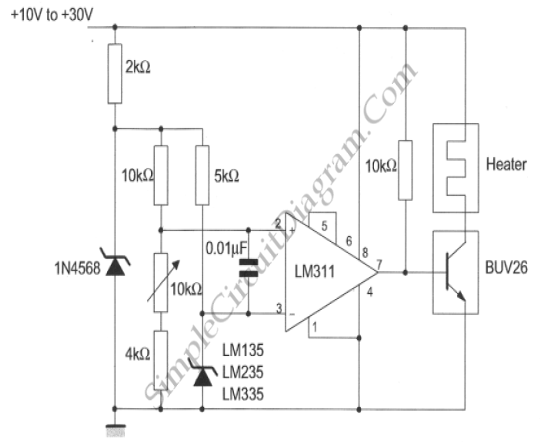
Simple Temperature Controller
This temperature controller utilizes an LM135/235/335 temperature sensor and is designed to maintain a small environment at a warm or hot temperature. A schematic diagram is provided.
The temperature controller circuit is centered around the LM135/235/335 series of temperature sensors, which...
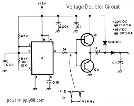
12V voltage doubler circuit
The schematic diagram originates from a 12V DC voltage doubler circuit power supply. This circuit diagram illustrates a DC voltage doubler/DC converter that transforms a 12V DC power supply into 24V DC and 18V DC outputs. It is compatible with...
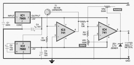
DIY Digital Thermometer Circuit
This DIY digital thermometer circuit can measure temperatures up to 150°C with an accuracy of ±1°C. The temperature is displayed on a 1V full scale deflection.
The digital thermometer circuit is designed to provide accurate temperature readings within a specified range,...
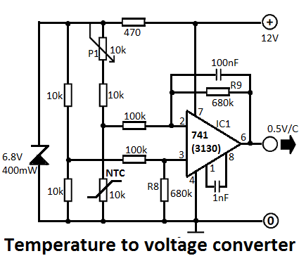
Temperature to Voltage Converter Circuit
This simple temperature-to-voltage converter circuit allows for precise measurement of room temperature using an NTC resistor or thermistor.
The temperature-to-voltage converter circuit typically employs a negative temperature coefficient (NTC) thermistor, which exhibits a decrease in resistance as temperature increases. This property...
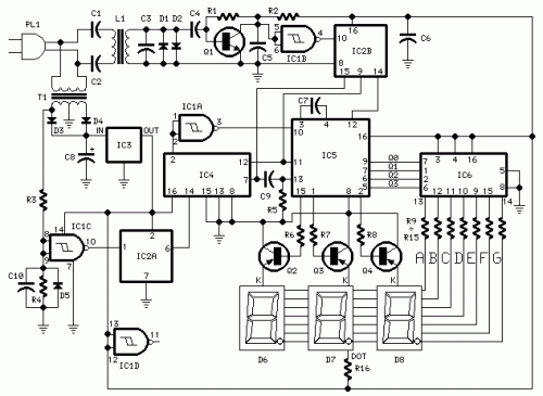
Digital Remote Thermometer
This circuit is designed for precise centigrade temperature measurement. It features a transmitter section that converts the sensor's output voltage, which is proportional to the measured temperature, into frequency. The output frequency bursts are transmitted through the mains supply cables....
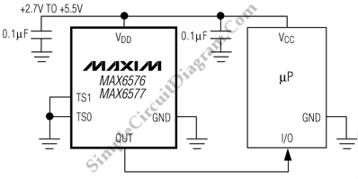
SOT Temperature Sensors with Period/Frequency Output
This is a low-current temperature sensor with a single-wire output. The number of pins required to interface with a microprocessor is minimized by this design.
The low-current temperature sensor operates efficiently by utilizing a single-wire communication protocol, which significantly reduces the...

thermometer circuit
When the system is placed in a shop or mall, logos and product advertisements serve as an ideal complement to temperature information. For home use, photographs of children at the beach or, should the temperature drop, images of making a...
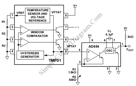
TMP01 AD654 Temperature-to-Frequency Converter
This is a TMP01 Temperature-to-Frequency Converter circuit. Converting voltage to the frequency domain is another common method of transmitting analog signals.
The TMP01 is a temperature sensor that outputs a frequency signal proportional to the temperature it measures. This circuit is...
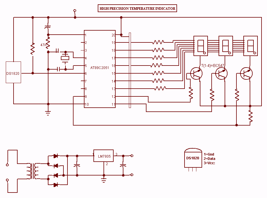
High Precision Temperature Indicator
This project is a high precision digital thermometer which indicates the temperature on the seven segment display. It has a resolution of 0.06 °C. The 1-wire temperature sensor IC from Maxim semiconductors is used as the sensor. The DS18S20 Digital...