


Electromyogram Monitor
#EMG
#amplifier
#signal conditioning
#differential amplifier
#electrode
#CMRR
#biomedical
#muscle activity
#measurement
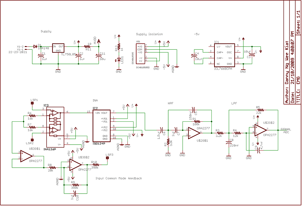
Description: Electrical potentials are generated by muscle when there is movement. This signal can be picked up by electrodes to form EMG. For my final year project, I did an amplifier and signal conditioning circuit for EMG. Attached below is the schematics for the amplifier. Disposable surface electrodes are used to pick up the signal. The amplitude of the signal picked up is low, so amplification is needed to measure the detected signal. A differential amplifier is needed because of the high CMRR. Two electrodes are connected in between the region of interest and the ground electrode is connected to a reference point. More: A driven feedback is implemented in the design to improve the signal quality. A second-order active low pass and active high pass are used to further amplify the signal and filter off the unwanted part of the signal. As the design uses a single supply, a 5V to -5V converter is used to power the active amplifier. An isolation amplifier and supply isolation are added as some basic safety implementation in the circuit.
The circuit described involves an electromyography (EMG) signal acquisition system designed to capture electrical signals generated by muscle contractions. The primary components include disposable surface electrodes that detect the electrical activity of muscles. Given the inherently low amplitude of the EMG signals, an amplification stage is critical for enhancing the signal to a measurable level.
A differential amplifier is employed in the design due to its high common-mode rejection ratio (CMRR), which is essential for minimizing noise and interference from external sources. The configuration typically involves two electrodes placed at the muscle site of interest, with a third ground electrode serving as a reference point to ensure accurate signal measurement.
To further enhance the quality of the acquired signal, a driven feedback mechanism is integrated into the design. This feedback helps stabilize the gain and improve the linearity of the amplifier. Additionally, second-order active filters, both low-pass and high-pass, are utilized to refine the signal. The low-pass filter allows for the retention of the desired frequency components while attenuating high-frequency noise, whereas the high-pass filter serves to eliminate low-frequency drift and interference.
As the circuit operates on a single supply voltage, a 5V to -5V converter is implemented to provide the necessary bipolar power supply for the active amplifiers. This is crucial for ensuring that the amplifier can operate effectively across the full range of the EMG signal.
Moreover, safety considerations are addressed through the inclusion of isolation amplifiers and supply isolation techniques. These components protect both the user and the sensitive electronics from potential electrical hazards, ensuring that the circuit can operate safely in a clinical or research environment.
Overall, the described circuit effectively captures and processes EMG signals, providing a robust platform for further analysis or real-time monitoring of muscle activity.Electrical potentials are generated by muscle when there is movement. This Signal can be pick up by electrode to form EMG. For my Final Year Project, I did an amplifier and signal conditioning circuit for EMG. Attached below is the schematics for the Amplifier. Disposable surface electrode are used to pick up the signal. The amplitude of the signal pick up is low, so amplification is needed to measure the detected signal. A differential amplifier is needed because of the high CMRR. 2 electrodes are connected in between the region of interest and the ground electrode is connected to a reference point.
A driven feedback is implemented in the design to improve the signal quality. 2nd order active low pass and active high pass are used to further amplify the signal and filter off the unwanted part of the signal. As the design uses single supply, a 5v to -5v converter is used to power the active amplifier. Isolation amplifier and supply isolation is added as some basic safety implementation in the circuit.
The circuit described involves an electromyography (EMG) signal acquisition system designed to capture electrical signals generated by muscle contractions. The primary components include disposable surface electrodes that detect the electrical activity of muscles. Given the inherently low amplitude of the EMG signals, an amplification stage is critical for enhancing the signal to a measurable level.
A differential amplifier is employed in the design due to its high common-mode rejection ratio (CMRR), which is essential for minimizing noise and interference from external sources. The configuration typically involves two electrodes placed at the muscle site of interest, with a third ground electrode serving as a reference point to ensure accurate signal measurement.
To further enhance the quality of the acquired signal, a driven feedback mechanism is integrated into the design. This feedback helps stabilize the gain and improve the linearity of the amplifier. Additionally, second-order active filters, both low-pass and high-pass, are utilized to refine the signal. The low-pass filter allows for the retention of the desired frequency components while attenuating high-frequency noise, whereas the high-pass filter serves to eliminate low-frequency drift and interference.
As the circuit operates on a single supply voltage, a 5V to -5V converter is implemented to provide the necessary bipolar power supply for the active amplifiers. This is crucial for ensuring that the amplifier can operate effectively across the full range of the EMG signal.
Moreover, safety considerations are addressed through the inclusion of isolation amplifiers and supply isolation techniques. These components protect both the user and the sensitive electronics from potential electrical hazards, ensuring that the circuit can operate safely in a clinical or research environment.
Overall, the described circuit effectively captures and processes EMG signals, providing a robust platform for further analysis or real-time monitoring of muscle activity.Electrical potentials are generated by muscle when there is movement. This Signal can be pick up by electrode to form EMG. For my Final Year Project, I did an amplifier and signal conditioning circuit for EMG. Attached below is the schematics for the Amplifier. Disposable surface electrode are used to pick up the signal. The amplitude of the signal pick up is low, so amplification is needed to measure the detected signal. A differential amplifier is needed because of the high CMRR. 2 electrodes are connected in between the region of interest and the ground electrode is connected to a reference point.
A driven feedback is implemented in the design to improve the signal quality. 2nd order active low pass and active high pass are used to further amplify the signal and filter off the unwanted part of the signal. As the design uses single supply, a 5v to -5v converter is used to power the active amplifier. Isolation amplifier and supply isolation is added as some basic safety implementation in the circuit.
Ears and Speakers Protector
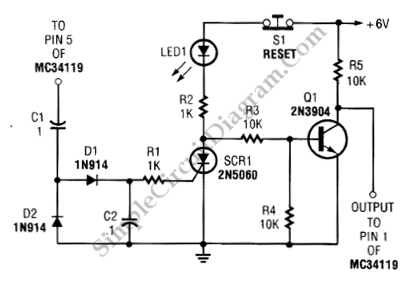
Occasionally, the output volume of an amplifier can be excessively high, leading to discomfort and potential damage to both the listener's ears and the loudspeaker. The circuit...
Amplifiers are crucial components in audio systems, responsible for boosting audio signals to drive...
Precision Measurement without Ground Offsets Using Differential Amplifier Input to A/D ADC
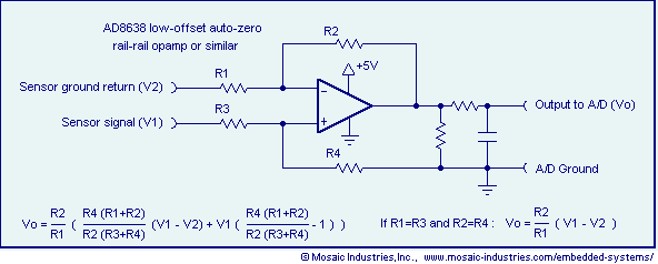
Ground loop offset errors and ground noise are eliminated by a differential amplifier or instrumentation amplifier before the analog-to-digital (A/D) conversion. The differential input amplifier addresses ground loop errors, allowing for precise measurement of non-isolated sensors. A simple operational amplifier...
Self Oscillating Amplifier for Distortion Testing
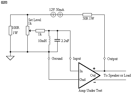
The circuit is based on a simple inductor-capacitor filter circuit, and needs only a pot and a small light bulb to set and stabilise the oscillation. The frequency is fixed, and with a good inductor should be capable of very...
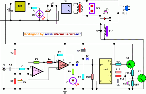
Amplifier Timer Circuit Schematic
This circuit turns off an amplifier or any other device when a low-level audio signal fed to its input is absent for at least 15 minutes. Pressing P1 switches the device on, supplying power to any appliance connected to SK1....
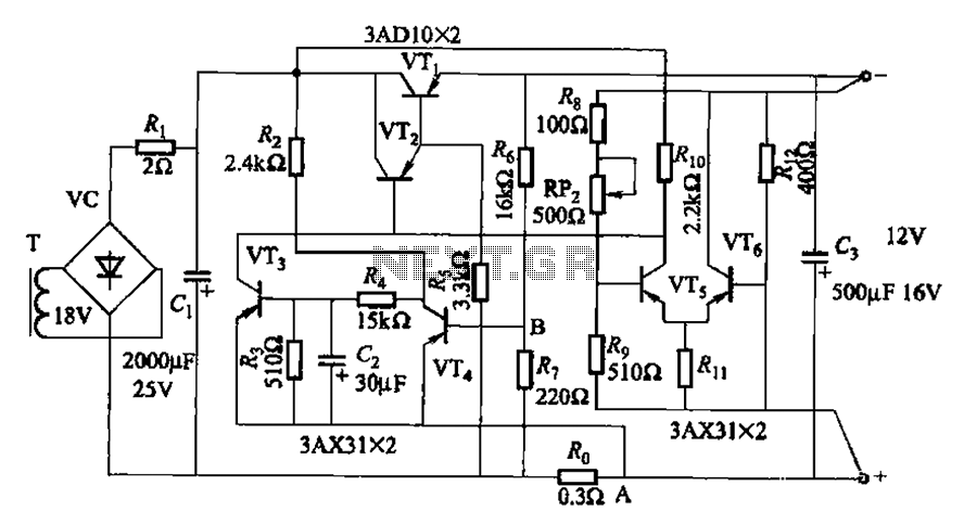
Having a differential amplifier and overcurrent protection for power supply circuit 2
The circuit features a current protection mechanism utilizing transistors VTa, VT4, and a sense resistor Ro. When an overcurrent or short-circuit fault occurs, the power supply cannot resume normal operation because the conduction condition of VT3 remains unchanged, resulting in...
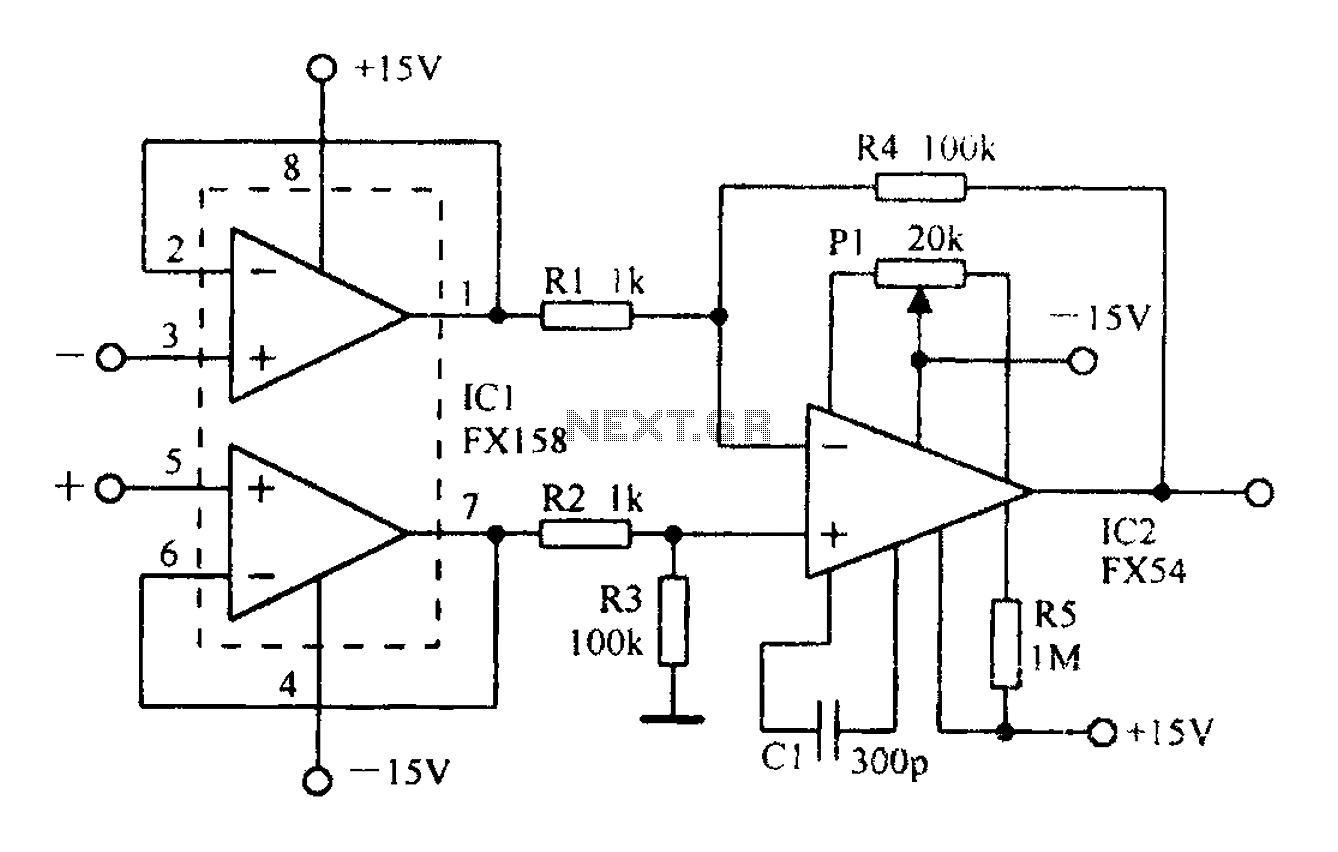
A differential amplifier having input impedance equal to the circuit diagram
A differential amplifier with input impedance as indicated in the circuit diagram.
A differential amplifier is a crucial component in various electronic applications, primarily used to amplify the difference between two input voltages while rejecting any common-mode signals. This characteristic makes...
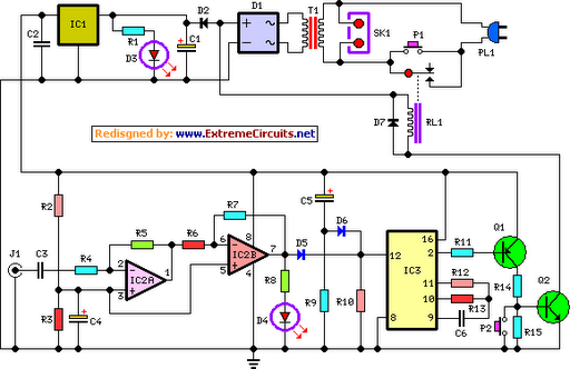
Amplifier Timer Circuit Schematic
This circuit deactivates an amplifier or any connected device when a low-level audio signal is absent at its input for at least 15 minutes. Activating switch P1 powers the device, enabling operation of any appliance connected to SK1. The input...
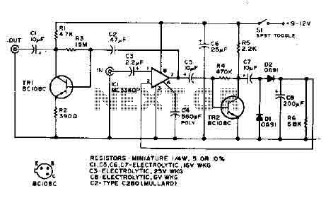
Amplifier Compressor MC3340P
The output is rectified, and TR2 controls the gain of the ICL. This audio compressor circuit uses an MC3340P as a variable gain amplifier.
The audio compressor circuit described utilizes an MC3340P integrated circuit, which functions as a variable gain amplifier...
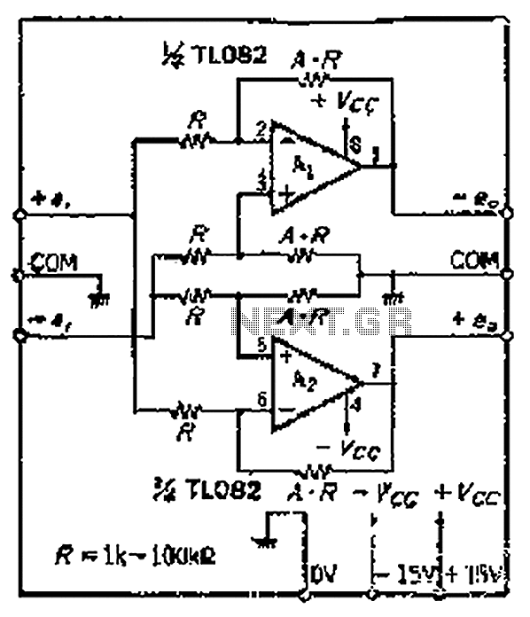
Output input can be balanced equilibrium Repeater
The circuit features a symmetric configuration of two basic differential amplifiers. The differential inputs, labeled +IN and -IN, are connected to ensure balanced input. The output signal components are inverted, resulting in a phase-coherent output. Although the circuit requires a...