


Flash-meter
#IGFET
#photo cell
#transformer
#voltage pulse
#rectifier
#flash detection
#light sensor
#pulse measurement
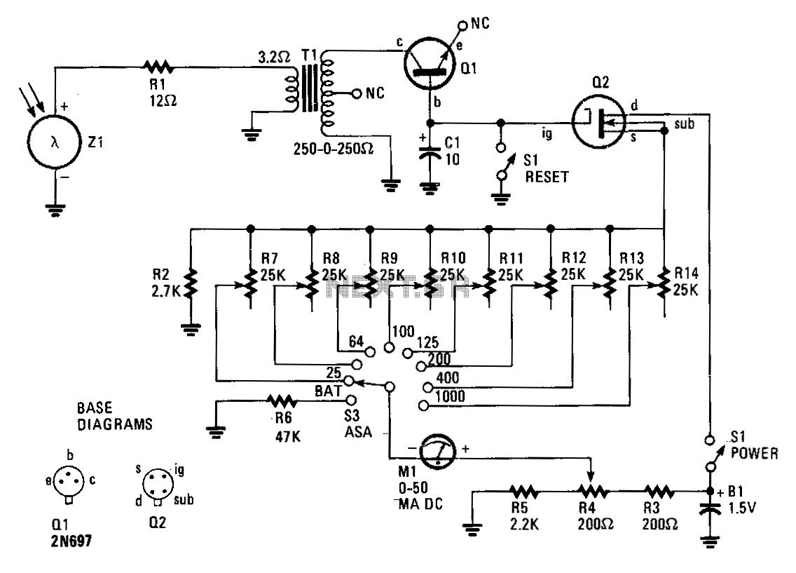
Description: The circuit comprises an insulated-gate field-effect transistor (IGFET) labeled Q2 and a silicon photo cell designated Z1. Transformer T1, an audio-output type, is configured in reverse within the circuit. When a sudden flash from a photoflash unit is detected by Z1, it generates a voltage pulse that travels through the low-impedance winding of T1 via resistor R1. This voltage pulse is then stepped up in the primary winding of T1, which has a resistance of 500 ohms, before being rectified by transistor Q1. Q1 is repurposed as a diode by having its emitter lead removed close to the case. Consequently, Q1 charges capacitor C1 to a voltage level that is proportional to the amplitude of the electrical pulse produced by the light from the flash unit.
Capacitor C1 regulates the current flowing through Q2, which features a very high input impedance. The current through Q2 is measured by meter M1, a direct current unit with a range of 0-50 microamperes, calibrated in f-stops. The exceptionally high internal resistances of both Q1 and Q2 allow C1 to maintain its charge for several minutes, providing ample time to take a reading from M1. The charge on C1 can be discharged to ground and reset to 0 V by pressing reset button S1, preparing the flashmate for the next photoflash. Trim potentiometers R7 through R14 are adjusted to specific values to ensure accurate readings corresponding to various film sensitivities or exposure indexes.
The described circuit operates effectively as a light intensity measurement device, utilizing the properties of IGFETs and photodetection to provide precise readings for photographic exposure settings. The unique configuration of the transformer allows for voltage amplification necessary to drive the rectification process, while the use of a modified transistor as a diode enhances the efficiency of charge accumulation in the capacitor. The calibration of the meter in f-stops ensures that users can directly relate the readings to photographic exposure requirements, making this circuit particularly useful for photographers seeking to optimize their settings based on ambient light conditions. The inclusion of trim potentiometers adds versatility, allowing for adjustments based on different film types or sensitivity ratings, ensuring that the device can cater to a broad range of photographic applications.Insulated-gate, field-effect transistor (IGFET), Q2 and silicon photo cell Zl form the heart of this circuit. Transformer T1 is an audio-output type, but it"s reversed in the circuit. A sudden flash from a photoflash unit detected by Zl sends a voltage pulse through the low-impedance winding of Tl via Rl.
That voltage pulse is stepped-up in Tl"s 500-!l, primary winding before being rectified by Ql. Transistor Ql is used as a diode; its emitter lead was snipped off close to the case. Ql then charges Cl to a value proportional to the amplitude of the electrical pulse generated by the light from a flash unit. Capacitor Cl controls the current flowing through Q2, which has a very high-input impedance. The current through Q2 is read by meter Ml, a 0-50 p.A de unit, which has been calibrated in f-stops. The extremely high internal resistances of Ql and Q2 will allow Cl to retain its charge for several minutes; this is more than enough time for you to take your reading of Ml.
The charge on Cl is shorted to ground and returned to 0 V by depressing reset button Sl. The flashmate is ready to read the next photoflash. Trim potentiometers, R7 through Rl4, are.adjusted to values which will yield correct readings for corresponding film sensitivities, or exposure indexes.
Capacitor C1 regulates the current flowing through Q2, which features a very high input impedance. The current through Q2 is measured by meter M1, a direct current unit with a range of 0-50 microamperes, calibrated in f-stops. The exceptionally high internal resistances of both Q1 and Q2 allow C1 to maintain its charge for several minutes, providing ample time to take a reading from M1. The charge on C1 can be discharged to ground and reset to 0 V by pressing reset button S1, preparing the flashmate for the next photoflash. Trim potentiometers R7 through R14 are adjusted to specific values to ensure accurate readings corresponding to various film sensitivities or exposure indexes.
The described circuit operates effectively as a light intensity measurement device, utilizing the properties of IGFETs and photodetection to provide precise readings for photographic exposure settings. The unique configuration of the transformer allows for voltage amplification necessary to drive the rectification process, while the use of a modified transistor as a diode enhances the efficiency of charge accumulation in the capacitor. The calibration of the meter in f-stops ensures that users can directly relate the readings to photographic exposure requirements, making this circuit particularly useful for photographers seeking to optimize their settings based on ambient light conditions. The inclusion of trim potentiometers adds versatility, allowing for adjustments based on different film types or sensitivity ratings, ensuring that the device can cater to a broad range of photographic applications.Insulated-gate, field-effect transistor (IGFET), Q2 and silicon photo cell Zl form the heart of this circuit. Transformer T1 is an audio-output type, but it"s reversed in the circuit. A sudden flash from a photoflash unit detected by Zl sends a voltage pulse through the low-impedance winding of Tl via Rl.
That voltage pulse is stepped-up in Tl"s 500-!l, primary winding before being rectified by Ql. Transistor Ql is used as a diode; its emitter lead was snipped off close to the case. Ql then charges Cl to a value proportional to the amplitude of the electrical pulse generated by the light from a flash unit. Capacitor Cl controls the current flowing through Q2, which has a very high-input impedance. The current through Q2 is read by meter Ml, a 0-50 p.A de unit, which has been calibrated in f-stops. The extremely high internal resistances of Ql and Q2 will allow Cl to retain its charge for several minutes; this is more than enough time for you to take your reading of Ml.
The charge on Cl is shorted to ground and returned to 0 V by depressing reset button Sl. The flashmate is ready to read the next photoflash. Trim potentiometers, R7 through Rl4, are.adjusted to values which will yield correct readings for corresponding film sensitivities, or exposure indexes.
Light-Controlled Pond Pump
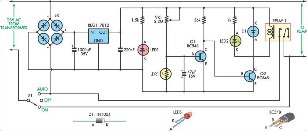
This circuit was designed to control a pump in a garden pond, enabling it to automatically activate at dawn and deactivate at dusk.
The circuit utilizes a light-dependent resistor (LDR) to detect ambient light levels, which serves as the primary sensor...
transformer Low voltage oscillator for joule thief
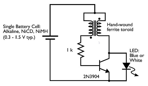
A transformer with two input leads and three output leads was used. An LED was connected to two of the output leads, and when a dead AA battery was connected to the input leads, the LED blinked for a brief...
power supply am farm radio
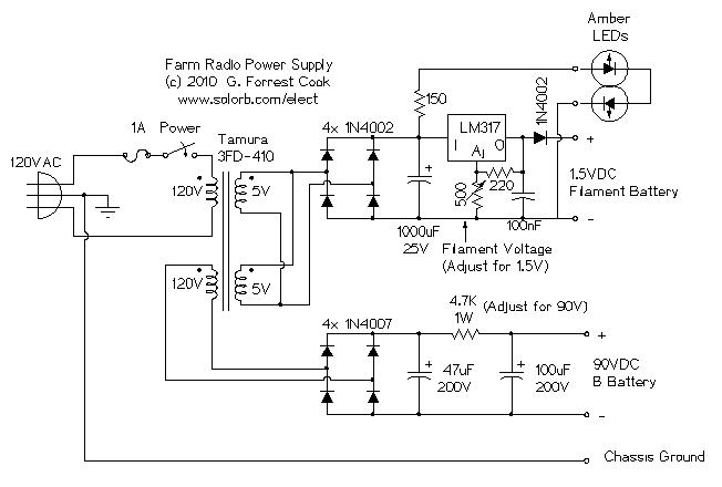
The ability accumulation is a Tamura 3FD-410 5V bifold primary/dual accessory transformer, available from DigiKey.com at reasonable prices. The transformer's primary windings can be configured in series for 240VAC operation or in parallel for 120VAC operation. This configuration utilizes one...
Light Sensor
The report provides information related to light sensors, photoresistors, comparators, and associated circuits. It contains extensive details regarding detection.
Light sensors are devices that detect and respond to light levels in the environment. A common type of light sensor is the...
CF1 CF2 main circuit
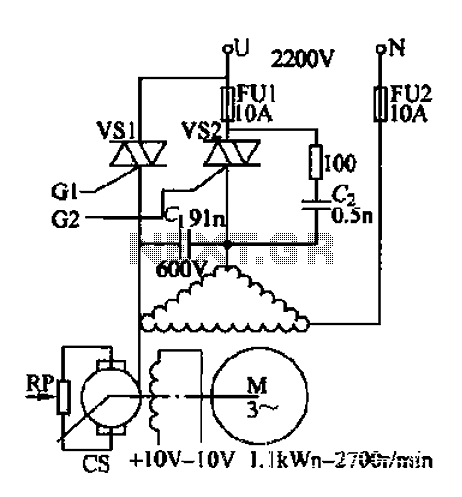
AC voltage is rectified by a bridge (VD1-VD4). A resistor (R1) limits the buck, while diode (VD5) provides clipping. A trapezoidal wave is generated as the trigger circuit for DC voltage and synchronization. When the base of transistor (VT1) receives...
Series DC power supply
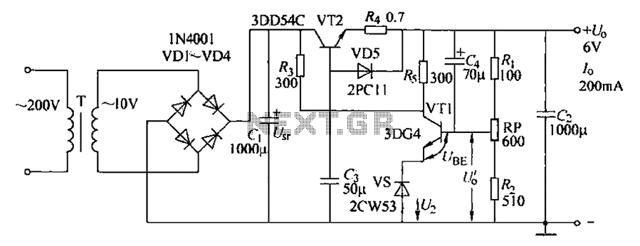
A power supply typically consists of a transformer, rectifier, filter, adjustment components, and reference power supply and sampling circuits. Additionally, it may include overload or short circuit protection devices. The circuit begins with a 220V step-down transformer (T) that converts...
How to properly snub transient spikes from a transformer and prevent switch mode power supply burn out
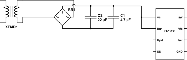
The leads from the transformer to the circuit are quite long (>5m). The 110V side of the transformer has been switched off frequently, which likely caused a spike on the secondary (24V) side. The input pin of the LTC3631 shows...
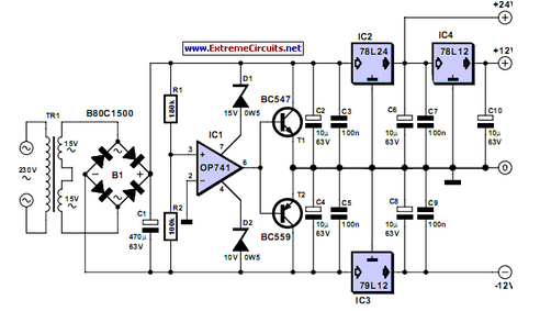
Triple Power Supply
Inexpensive miniature transformers typically offer one or two secondary voltages, which are adequate for producing a set of positive and negative supply voltages.
Miniature transformers are compact devices commonly utilized in various electronic applications, particularly in power supply circuits. These transformers...
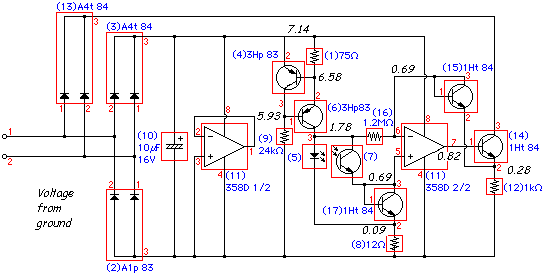
LEGO Light SensorCircuit With LM358 IC
The following circuit illustrates a LEGO Light Sensor Circuit Diagram. This circuit is based on the LM358 integrated circuit, which features a dual operational amplifier and high-speed capabilities.
The LEGO Light Sensor Circuit utilizes the LM358, a versatile dual op-amp IC,...