


Force Sensitive Resistor Round 0.5 Retail

Description: The 0.5" force-sensitive resistor (FSR) is an efficient component for measuring pressure and is straightforward to set up. The FSR alters its resistance based on the amount of pressure applied to its sensing area; more force results in lower resistance. When no pressure is applied, the sensor exhibits a resistance greater than 1MΩ. A resistor value of 27kΩ is selected to maximize the output voltage range from 0-5V, assuming the sensing range of the sensor is 0-100kΩ. The sensor is connected to jumper wires and a 27kΩ resistor, with the output voltage linked to the A0 pin of an Arduino Uno. For those unfamiliar with soldering, it is advisable to consult a Soldering 101 tutorial. This circuit allows for reading the Analog 0 input, with the Arduino returning a value between 0 and 1023, where 1023 corresponds to 5V. The output value decreases when pressure is applied, confirming the circuit's functionality. To calculate the resistance value of the sensor, the voltage divider equation can be utilized. In this scenario, the Arduino measures VO. Given that the output ranges from 0-1023 (with 1023 equal to 5V), VI can be replaced with 1023. Knowing R1 is 27kΩ, the equation simplifies accordingly. This equation for Rfsr is only valid for the 27kΩ resistor value of R1. The Arduino sketch can incorporate the value read from A0 as VO to print the resistance of the FSR.
To find the actual weight applied to the sensor, reference the graph in the datasheet for theoretical values or calibrate the circuit using a known weight. The provided example sketch for the 0.5" Force Sensitive Resistor includes a setup for the FSR as R2 in a voltage divider circuit with R1 set to 27kΩ, with Vout connected to Analog input 0. This sketch prints the resistance value of the FSR, with a warning that the resistance value is only valid for a 27kΩ resistor. If a different resistor value is employed, the equation x = (Rfsr / (R1 + Rfsr)) * 1023 should be used, where x is the value from A0 and R1 is the non-FSR resistor, to determine the FSR resistance in ohms.
The Arduino sketch defines FORCE as a float variable and initializes resistance as another float variable. In the setup function, the serial communication is initiated at a baud rate of 9600, and a message indicating the test of the 0.5" Force Sensitive Resistor is printed. The loop function continuously reads the analog value from the FORCE pin, calculates the resistance using the formula resistance = (26.4 * value) / (1 - (value / 1023.0)), and prints the resistance value. A delay of 200 milliseconds ensures a readable output frequency.
This sketch provides an approximate resistance of the FSR, which can then be correlated to the actual force applied. It is essential to note that the actual force experienced by the resistor is significantly influenced by the specific implementation and tolerance of the FSR being utilized. For accurate weight determination, calibration of the sensor with a known force is recommended to establish an empirical force/resistance curve. The sensor is particularly well-suited for applications involving weight shifts and relative force detection.The 0. 5" force sensitive resistor (FSR) is a quick way to measure pressure, and is very easy to setup. The FSR varies its resistance depending on how much pressure is applied to the sensing area. The greater the force, the lower the resistance. When measured with a multimeter, the sensor has a resistance of greater than 1M © when no pressure is ap plied. The value of 27k © was chosen to give the output voltage the greatest "sweep" from 0-5V, assuming that the sensing range (resistance sweep) of the sensor is 0-100k ©. The sensor is soldered to jumper wires and another (27k ©) resistor, with the output voltage connected to A0 of the Uno.
If you`re new to soldering, be sure to read the Soldering 101 Tutorial. Using this circuit, we can simply read the Analog 0 input, and the Arduino will return a value somewhere between 0 and 1023, with 1023 representing 5V. The value decreases when pressure is applied to the sensor. This proves that the circuit is working, but what if we want to calculate the resistance value of the sensor We can find this using the equation for a voltage divider: In this case, the Arduino is measuring VO.
Since its output is 0-1023, with 1023 representing 5V, we can replace VI with 1023. Also, since we know that the value of R1 is 27k ©, this equation becomes: Note that this equation for Rfsr only works for the 27k © resistor value of R1. We can now plug this in to our Arduino sketch, using the value read from A0 as VO, and print out the resistance of the FSR.
// <7465> * //ExampleSketchforthe0. 5"ForceSensitiveResistor //3/17/11 // //SetuptheFSRasR2ofvoltagedividercircuitwithR1avalueof27k //VoutconnectedtoAnaloginput0 //PrintsresistancevalueofFSR // //WARNING:Resistancevalueonlyvalidfor27kresistorifusingadifferent //value, usetheequation // //x=(Rfsr/(R1+Rfsr)*1023 // //wherexisthevaluefromA0, andR1isthenon-FSRresistor, tofindthe //FSRresistanceinOhms. // //Tofindtheactualweightappliedtothesensor, refertothegraphonpage //5ofthedatasheet(theoreticalvaluesonly!)orcalibratethecircuitus ing //ofaknownweight.
// <7465> * #defineFORCE0 float value = 0; float resistance = 0; void setup() { Serial. begin(9600); Serial. println("0. 5" Force Sensitive Resistor Test"); } void loop() { value=analogRead(FORCE); resistance=(26. 4*value)/(1-(value/1023. 0); Serial. println(resistance, DEC); delay(200); } This sketch will print the approximate resistance of the FSR in order to translate this resistance into the actual force applied. You can reference the graph on page five of the FSR datasheet: Please note, however, that the actual force applied to the resistor depends heavily on the particular implementation and the tolerance of the specific FSR you`re using.
In order to determine an actual weight, it is recommended that you calibrate the sensor with a known force in order to form an empirical force/resistance curve. Otherwise, this sensor is great for detecting things like weight shift and relative force.
To find the actual weight applied to the sensor, reference the graph in the datasheet for theoretical values or calibrate the circuit using a known weight. The provided example sketch for the 0.5" Force Sensitive Resistor includes a setup for the FSR as R2 in a voltage divider circuit with R1 set to 27kΩ, with Vout connected to Analog input 0. This sketch prints the resistance value of the FSR, with a warning that the resistance value is only valid for a 27kΩ resistor. If a different resistor value is employed, the equation x = (Rfsr / (R1 + Rfsr)) * 1023 should be used, where x is the value from A0 and R1 is the non-FSR resistor, to determine the FSR resistance in ohms.
The Arduino sketch defines FORCE as a float variable and initializes resistance as another float variable. In the setup function, the serial communication is initiated at a baud rate of 9600, and a message indicating the test of the 0.5" Force Sensitive Resistor is printed. The loop function continuously reads the analog value from the FORCE pin, calculates the resistance using the formula resistance = (26.4 * value) / (1 - (value / 1023.0)), and prints the resistance value. A delay of 200 milliseconds ensures a readable output frequency.
This sketch provides an approximate resistance of the FSR, which can then be correlated to the actual force applied. It is essential to note that the actual force experienced by the resistor is significantly influenced by the specific implementation and tolerance of the FSR being utilized. For accurate weight determination, calibration of the sensor with a known force is recommended to establish an empirical force/resistance curve. The sensor is particularly well-suited for applications involving weight shifts and relative force detection.The 0. 5" force sensitive resistor (FSR) is a quick way to measure pressure, and is very easy to setup. The FSR varies its resistance depending on how much pressure is applied to the sensing area. The greater the force, the lower the resistance. When measured with a multimeter, the sensor has a resistance of greater than 1M © when no pressure is ap plied. The value of 27k © was chosen to give the output voltage the greatest "sweep" from 0-5V, assuming that the sensing range (resistance sweep) of the sensor is 0-100k ©. The sensor is soldered to jumper wires and another (27k ©) resistor, with the output voltage connected to A0 of the Uno.
If you`re new to soldering, be sure to read the Soldering 101 Tutorial. Using this circuit, we can simply read the Analog 0 input, and the Arduino will return a value somewhere between 0 and 1023, with 1023 representing 5V. The value decreases when pressure is applied to the sensor. This proves that the circuit is working, but what if we want to calculate the resistance value of the sensor We can find this using the equation for a voltage divider: In this case, the Arduino is measuring VO.
Since its output is 0-1023, with 1023 representing 5V, we can replace VI with 1023. Also, since we know that the value of R1 is 27k ©, this equation becomes: Note that this equation for Rfsr only works for the 27k © resistor value of R1. We can now plug this in to our Arduino sketch, using the value read from A0 as VO, and print out the resistance of the FSR.
// <7465> * //ExampleSketchforthe0. 5"ForceSensitiveResistor //3/17/11 // //SetuptheFSRasR2ofvoltagedividercircuitwithR1avalueof27k //VoutconnectedtoAnaloginput0 //PrintsresistancevalueofFSR // //WARNING:Resistancevalueonlyvalidfor27kresistorifusingadifferent //value, usetheequation // //x=(Rfsr/(R1+Rfsr)*1023 // //wherexisthevaluefromA0, andR1isthenon-FSRresistor, tofindthe //FSRresistanceinOhms. // //Tofindtheactualweightappliedtothesensor, refertothegraphonpage //5ofthedatasheet(theoreticalvaluesonly!)orcalibratethecircuitus ing //ofaknownweight.
// <7465> * #defineFORCE0 float value = 0; float resistance = 0; void setup() { Serial. begin(9600); Serial. println("0. 5" Force Sensitive Resistor Test"); } void loop() { value=analogRead(FORCE); resistance=(26. 4*value)/(1-(value/1023. 0); Serial. println(resistance, DEC); delay(200); } This sketch will print the approximate resistance of the FSR in order to translate this resistance into the actual force applied. You can reference the graph on page five of the FSR datasheet: Please note, however, that the actual force applied to the resistor depends heavily on the particular implementation and the tolerance of the specific FSR you`re using.
In order to determine an actual weight, it is recommended that you calibrate the sensor with a known force in order to form an empirical force/resistance curve. Otherwise, this sensor is great for detecting things like weight shift and relative force.
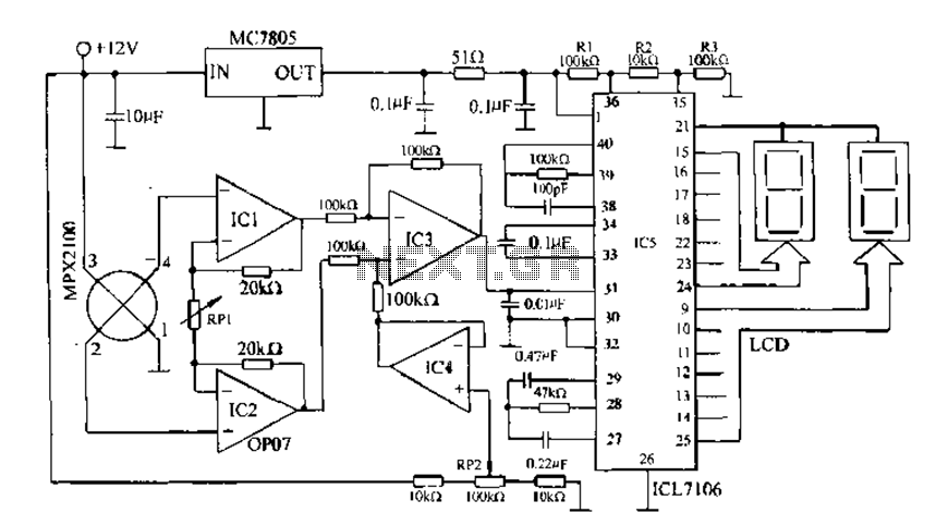
Digital pressure measuring circuit
Digital pressure measuring circuit using AD7710/7715/7730 multifunction digital sensor signal conditioning ICs. These ICs integrate a digital interface with the control port, a clock generator, a digital filter, amplitude modulation, a programmable gain amplifier, an A/D converter, and other electronic...
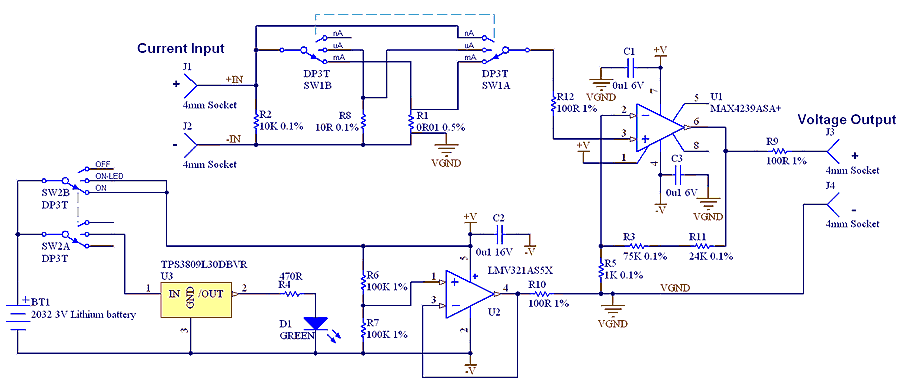
µCurrent Adaptor for multimeters
The µCurrent is in many cases also able to improve upon your meters current range accuracy by using your meters more accurate mVDC or mVAC voltage ranges instead to display the DC or AC current. With AC the frequency response...
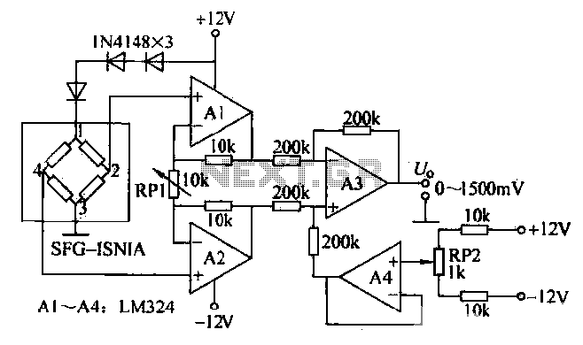
Pressure measurement circuit diagram
This is a measurement circuit designed to measure forces ranging from 0 to 1500 grams, producing an output voltage of 0 to 1500 millivolts (mV) with a sensitivity of 1 mV per gram. The circuit is powered by a 12V...
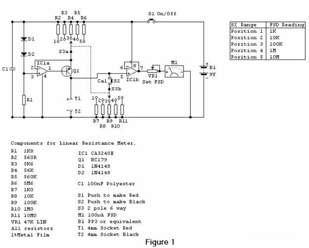
Linear Resistance Meter
Most analog multimeters are capable of measuring resistance over a wide range of values, but they can be inconvenient to use due to the reverse reading scale, which is also non-linear.
Analog multimeters, often referred to as VOMs (Volt-Ohm-Milliammeter), are versatile...
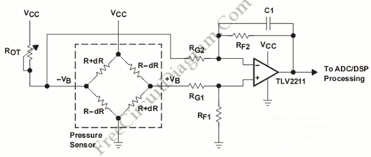
Pressure Sensor Signal Conditioning Circuit with Single Op-Amp
This is a pressure sensor signal conditioning circuit. It is a simple and inexpensive circuit due to its small geometry and the use of a straightforward pressure sensor.
The pressure sensor signal conditioning circuit is designed to convert the raw output...
Pressure measurement circuit diagram
This is a measurement circuit designed to measure forces ranging from 0 to 1500 grams, producing an output voltage of 0 to 1500 millivolts (mV) with a sensitivity of 1 mV per gram. The circuit is powered by a 12V...
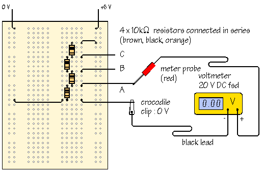
using a multimeter
A meter is a measuring instrument. An ammeter measures current, a voltmeter measures the potential difference (voltage) between two points, and an ohmmeter measures resistance. A multimeter combines these functions, and possibly some additional ones, into a single instrument. Before...
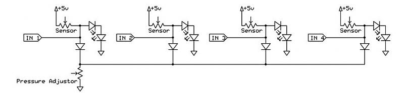
pressure sensor circuit
A dance pad consists of four pressure sensors (up, down, left, right). A USB controller has already been created for the dance pad, and the next step involves connecting the actual sensors. The intention is to pull the input down...
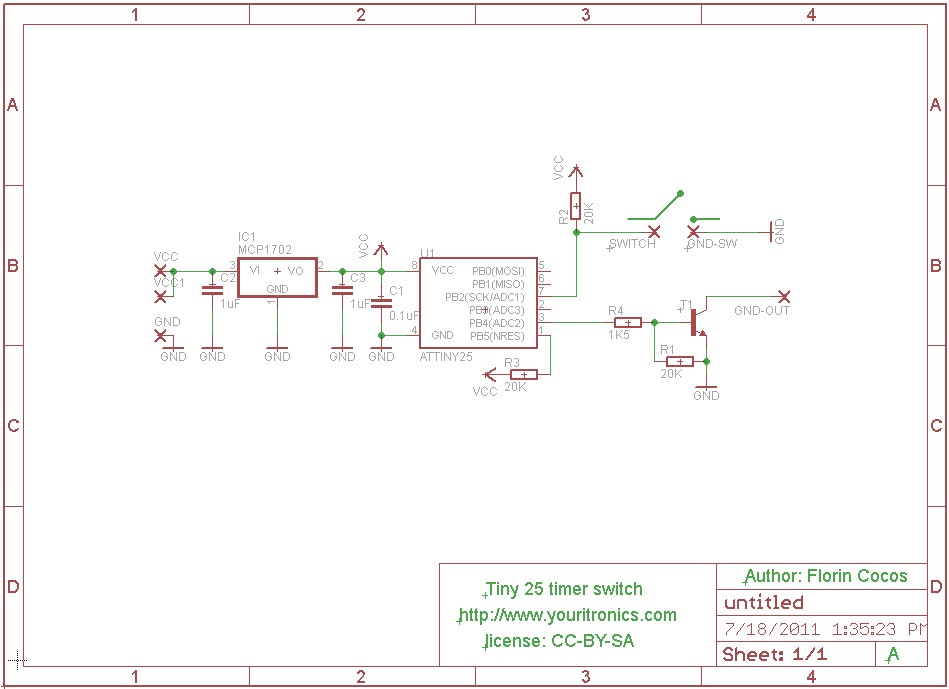
How to Add Auto Turn-Off to a Multimeter
Most multimeters today have an auto turn-off feature built in. There is enough space in a multimeter enclosure, so why not install a simple circuit that...
A multimeter's auto turn-off feature is designed to conserve battery life by shutting down the...