


HALL SENSOR CURRENT MONITOR
#Hall-effect sensor
#current measurement
#toroid
#dc current
#automotive
#flux-collector
#linear output
#low power
#40A range
#voltage proportional
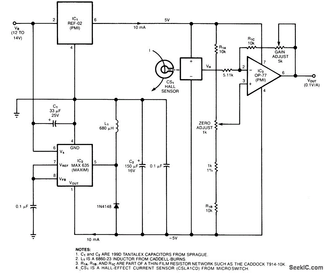
Description: The circuit utilizes a Hall-effect sensor, which is an integrated circuit (IC) positioned within a small gap of a flux-collector toroid, to measure direct current (DC) ranging from 1 to 40 A. The current-carrying wire is threaded through the toroid, allowing the Hall voltage (VH) to be linearly proportional to the current (I). The current draw from the voltage source (VB) is less than 30 mA. This setup is designed to monitor an automobile alternator.
The Hall-effect sensor circuit operates based on the principle of the Hall effect, which states that a voltage is generated perpendicular to both the magnetic field and the current flow in a conductor. In this configuration, as the current flows through the wire wrapped around the toroid, it generates a magnetic field proportional to the current. The Hall-effect sensor detects this magnetic field and produces a corresponding Hall voltage.
The toroid serves as a magnetic core that enhances the magnetic field produced by the current, allowing for more accurate measurements. The linear relationship between the Hall voltage and the current enables straightforward calculations to determine the current flowing through the wire based on the measured voltage. The IC typically includes signal conditioning circuitry to amplify and filter the Hall voltage, ensuring that the output is suitable for further processing or display.
In automotive applications, this current measurement is crucial for monitoring the performance of the alternator, ensuring that it operates within its specified parameters. The low current drain from the power supply (VB) ensures minimal impact on the vehicle's electrical system, making the circuit efficient and reliable.
This Hall-effect sensor circuit can be integrated into larger monitoring systems, providing real-time feedback on electrical performance and aiding in diagnostics and maintenance of the vehicle's electrical components. The design can be adapted for various applications beyond automotive use, including industrial equipment and renewable energy systems, where current measurement is essential for operational efficiency and safety.The circuit uses a Hall-effect sensor, which consists of an IC that resides in a small gap in a flux-collector toroid, to measure dc current from 1 to 40 A. Wrap the current-carrying wire through the toroid; the Hall voltage VH is then linearly proportional to the current (I).
The current drain from VB is less than 30 mA. To monitor an automobile alternat..
The Hall-effect sensor circuit operates based on the principle of the Hall effect, which states that a voltage is generated perpendicular to both the magnetic field and the current flow in a conductor. In this configuration, as the current flows through the wire wrapped around the toroid, it generates a magnetic field proportional to the current. The Hall-effect sensor detects this magnetic field and produces a corresponding Hall voltage.
The toroid serves as a magnetic core that enhances the magnetic field produced by the current, allowing for more accurate measurements. The linear relationship between the Hall voltage and the current enables straightforward calculations to determine the current flowing through the wire based on the measured voltage. The IC typically includes signal conditioning circuitry to amplify and filter the Hall voltage, ensuring that the output is suitable for further processing or display.
In automotive applications, this current measurement is crucial for monitoring the performance of the alternator, ensuring that it operates within its specified parameters. The low current drain from the power supply (VB) ensures minimal impact on the vehicle's electrical system, making the circuit efficient and reliable.
This Hall-effect sensor circuit can be integrated into larger monitoring systems, providing real-time feedback on electrical performance and aiding in diagnostics and maintenance of the vehicle's electrical components. The design can be adapted for various applications beyond automotive use, including industrial equipment and renewable energy systems, where current measurement is essential for operational efficiency and safety.The circuit uses a Hall-effect sensor, which consists of an IC that resides in a small gap in a flux-collector toroid, to measure dc current from 1 to 40 A. Wrap the current-carrying wire through the toroid; the Hall voltage VH is then linearly proportional to the current (I).
The current drain from VB is less than 30 mA. To monitor an automobile alternat..
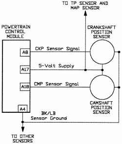
Camshaft Position Sensor
AutoZone Repair Guide for Engine Performance and Emission Control Components and Systems, specifically focusing on the Camshaft Position Sensor.
The Camshaft Position Sensor (CMP) is a critical component in modern internal combustion engines, playing a vital role in the management of...
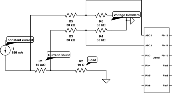
voltage measurement Measure current on a constant current source
Measure current on a constant current source (LM317). Since a 3.3V chip is being used, a voltage divider is also required for reading the current. Will this circuit function correctly, or will it cause issues by attempting to increase voltage...
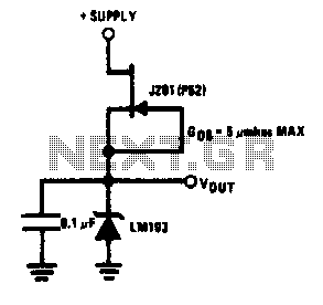
Low power regulator reference
This simple reference circuit provides a stable voltage reference that is nearly free from supply voltage noise. Typical power supply rejection exceeds 100 dB.
The described voltage reference circuit is designed to deliver a consistent output voltage while minimizing the influence...
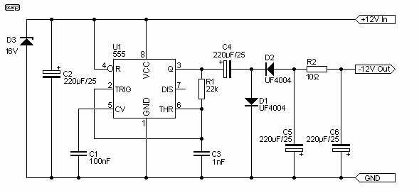
Low Power Negative Car Power Supply
I have had a lot of queries about getting a low power negative supply in cars, to power Linkwitz transform circuits and the like. There is a switchmode converter, but I must admit that it is overkill for what most...
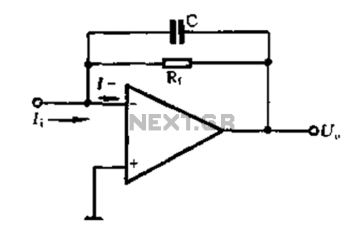
A current - voltage conversion circuit
A current-voltage conversion circuit.
A current-voltage conversion circuit is designed to transform an input current signal into a corresponding voltage signal. This type of circuit is fundamental in various applications, including sensor interfacing, signal conditioning, and analog-to-digital conversion processes.
Typically, the...
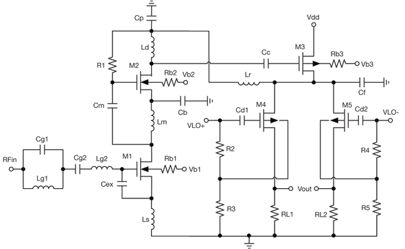
low power receiver serves multiple wireless standards
By combining a current-reuse amplifier and a switch-based mixer, a dual-band receiver front end offers excellent performance with extremely low power consumption.
The dual-band receiver front end integrates a current-reuse amplifier and a switch-based mixer to achieve high performance while maintaining...
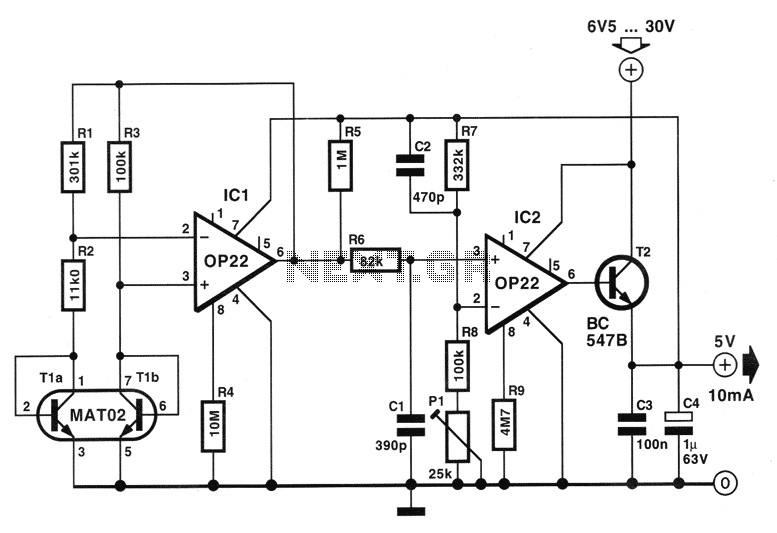
Low Power consumption 5V regulator circuit
The circuit described below is notable for its low power consumption. With a 9V input and no load at the output, it draws only 50 mA, which is significantly lower than the quiescent current of a 78L05 regulator. The circuit...
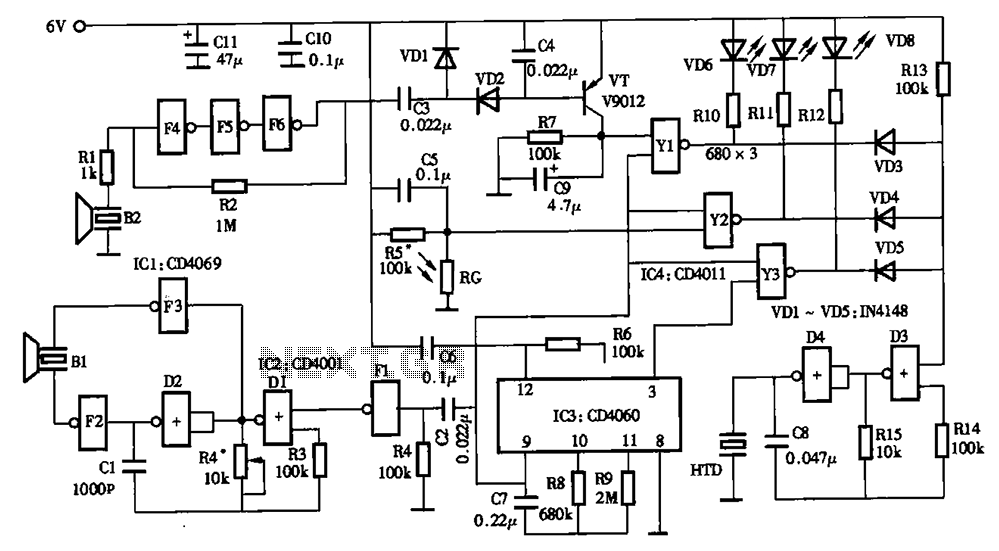
Low power timer switch
The timing circuit utilizes an electronic switch composed of F1, F2, and VT1 to reduce quiescent current to approximately 1 to 2 A with the 555 timer. Upon initial power-up, the voltage across capacitor C2 cannot instantly change, causing the...
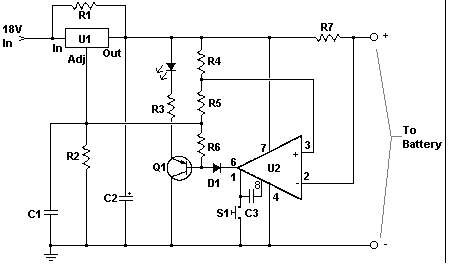
Car battery charger Automative car and motorcycle schematics
The circuit is designed to operate with an external power supply, which is why it does not include a transformer, rectifier, or filter capacitors in the schematic. However, these components can be added if desired. To utilize the circuit, connect...