


Heart Rate Sensor
#heart rate
#phototransistor
#light reflectance
#biometric
#health monitoring
#sensor
#wiring
#circuit schematic
#medical electronics
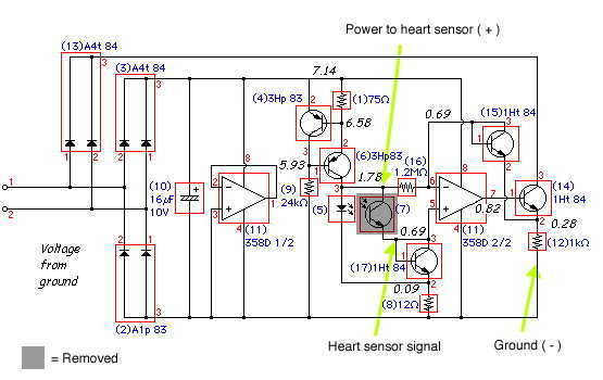
Description: Here is the inside of the light reflectance sensor (top) and a schematic drawing of its circuitry (bottom). First, carefully remove the phototransistor as shown. Then, attach the three wires that we will connect to the heart sensor (shown in bright yellow). Hint: if you leave the leads from the phototransistor when you cut it off, you can attach the two corresponding wires directly to them, rather than to the circuit board itself.
The light reflectance sensor typically consists of a phototransistor, which is the primary component for detecting light levels. The schematic drawing illustrates the connections and layout of the circuit, emphasizing the importance of proper wiring to ensure accurate readings. The phototransistor, when exposed to light, generates a current that can be measured and interpreted by the connected heart sensor.
In the assembly process, careful removal of the phototransistor is crucial to maintain the integrity of the circuit. Once the phototransistor is detached, the three wires intended for connection to the heart sensor must be securely attached. The use of the existing leads from the phototransistor can simplify this process, allowing for a more straightforward connection without needing to solder directly onto the circuit board.
The schematic also indicates the placement of resistors and capacitors that may be present in the circuit, which can help stabilize the output signal and filter any noise that may interfere with the sensor's performance. Proper attention to these components will enhance the reliability of the light reflectance sensor in measuring light intensity, which is essential for accurate heart rate monitoring in various applications.Here is the inside of the light reflectance sensor (top) and a schematic drawing of it's circuitry (bottom). First, carefully remove the phototransistor as shown. Then, attach the three wires that we will connect to the heart sensor (show in bright yellow). Hint: if you leave the leads from the phototransistor when you cut it off, you can attach the two corresponding wires directly to them, rather than to the circuit board itself.
The light reflectance sensor typically consists of a phototransistor, which is the primary component for detecting light levels. The schematic drawing illustrates the connections and layout of the circuit, emphasizing the importance of proper wiring to ensure accurate readings. The phototransistor, when exposed to light, generates a current that can be measured and interpreted by the connected heart sensor.
In the assembly process, careful removal of the phototransistor is crucial to maintain the integrity of the circuit. Once the phototransistor is detached, the three wires intended for connection to the heart sensor must be securely attached. The use of the existing leads from the phototransistor can simplify this process, allowing for a more straightforward connection without needing to solder directly onto the circuit board.
The schematic also indicates the placement of resistors and capacitors that may be present in the circuit, which can help stabilize the output signal and filter any noise that may interfere with the sensor's performance. Proper attention to these components will enhance the reliability of the light reflectance sensor in measuring light intensity, which is essential for accurate heart rate monitoring in various applications.Here is the inside of the light reflectance sensor (top) and a schematic drawing of it's circuitry (bottom). First, carefully remove the phototransistor as shown. Then, attach the three wires that we will connect to the heart sensor (show in bright yellow). Hint: if you leave the leads from the phototransistor when you cut it off, you can attach the two corresponding wires directly to them, rather than to the circuit board itself.
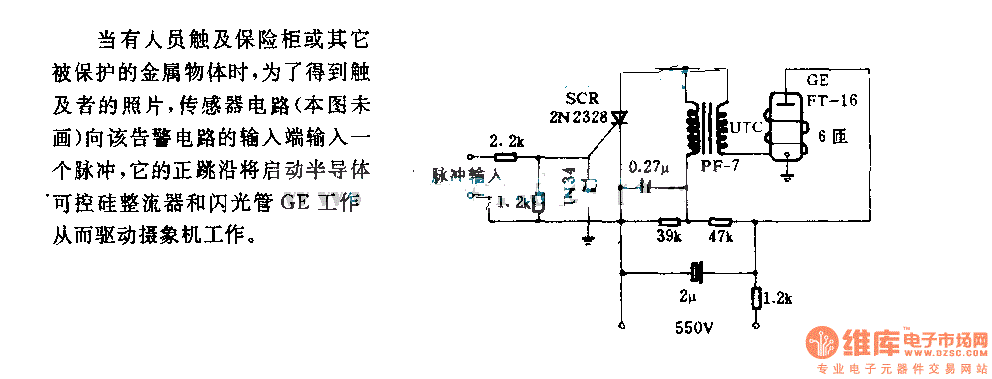
The alarm circuit diagram for safety box and other metal objects
When an individual touches the safety box or other protected metal objects, the sensor circuit generates a pulse to the alarm circuit. The positive edge of this pulse activates the semiconductor and thyristor flash GE, subsequently triggering the camera to...
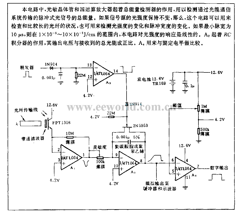
Optical transmission detection circuit
This circuit employs a phototransistor along with four operational amplifiers to function as a total energy detector. It is designed to measure the total energy of optical pulses transmitted through an optical cable communication system. When the light intensity of...
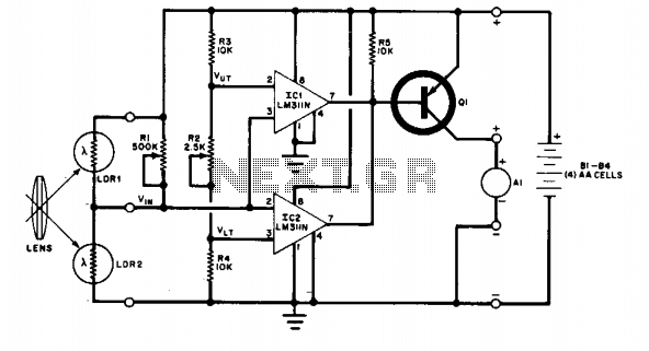
Field disturbance sensor-alarm
The change in ambient light triggers the alarm by changing the resistance of LDR1 and LDR2.
The circuit utilizes two light-dependent resistors (LDR1 and LDR2) to detect variations in ambient light levels. LDRs are passive components that exhibit a change in...
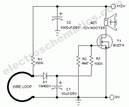
Wire Break Sensor Alarm Circuit Schematic
The circuit of a loop sensor-based simple security alarm is described here. The sensor loop consists of a short length of thin enamelled copper wire.
The loop sensor security alarm operates on the principle of detecting interruptions in the circuit formed...

simple optical switch
When the phototransistor is illuminated by infrared (IR) light, it begins to conduct, causing the voltage between a 1 MΩ resistor (chosen arbitrarily) and the phototransistor to decrease from VCC to lower values. When this voltage falls below VCC/3, the...

Esquire Wiring
The most likely issue with the wiring is the individual responsible for it. Apologies for the lengthy post, but providing more information and pictures may help clarify the situation.
To create a comprehensive electronic schematic description, it is essential to focus...
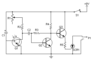
Flash Slave Trigger
Flash slaves are utilized to enhance a primary flash unit by adding one or more supplementary flash units. The slave trigger detects the initial flash through a phototransistor and subsequently activates the additional flashes with a delay of a few...
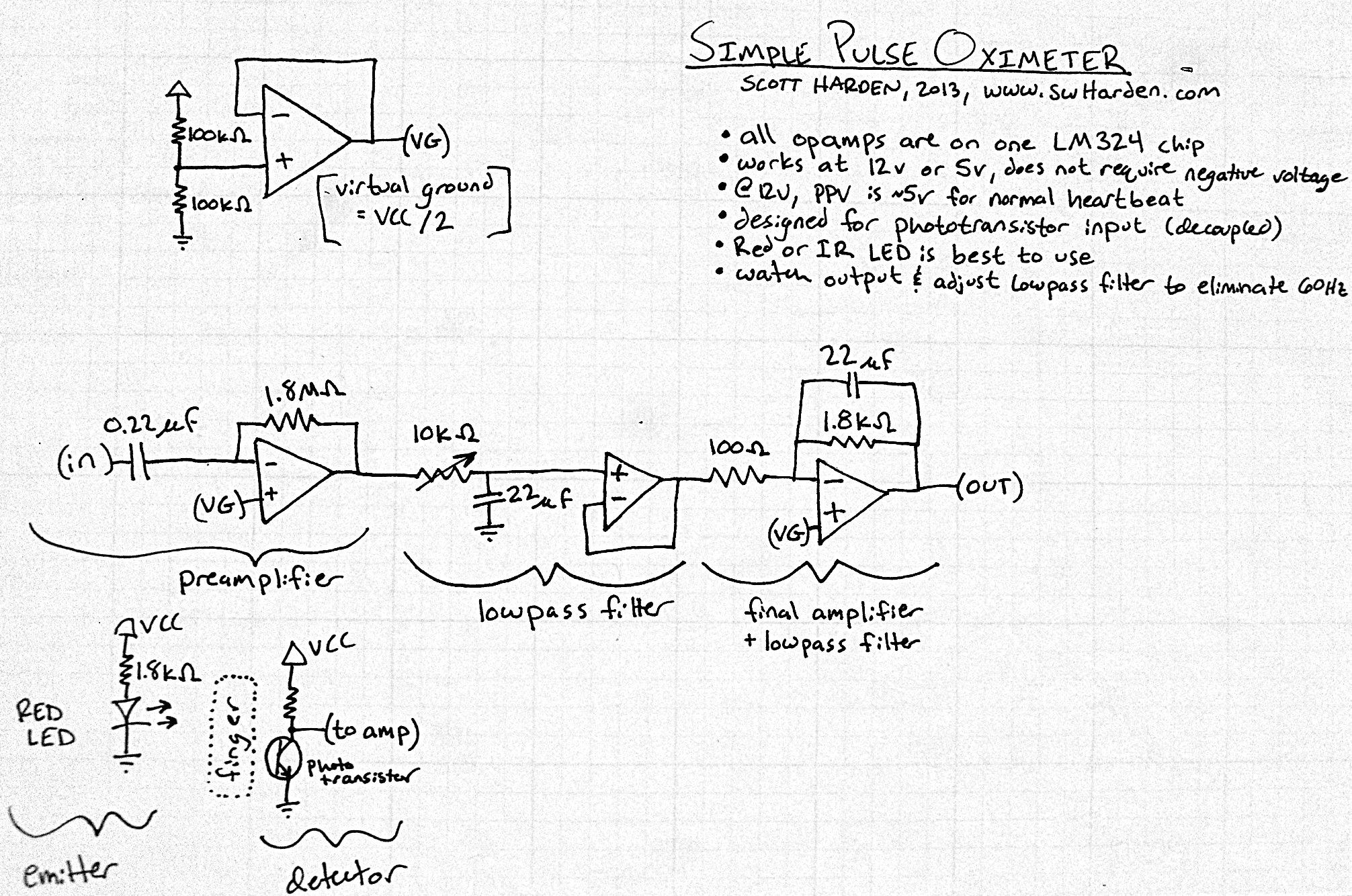
Pulse meter circuit
The input capacitor for the phototransistor at the bottom is responsible for feeding the operational amplifier (op-amp). However, the output from the phototransistor consistently remains between ground (GND) and the supply voltage (Vcc). The necessity for an input capacitor arises...
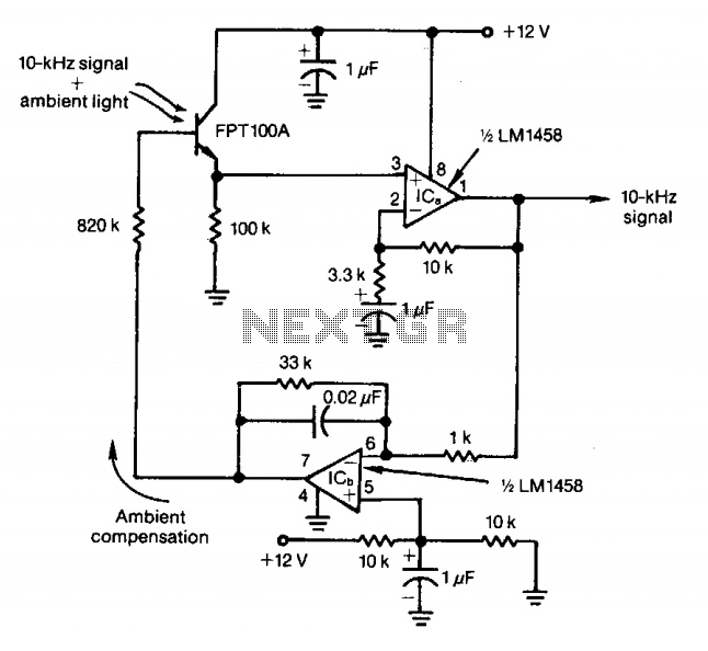
Modulated light-beam circuit
The feedback control of the phototransistor in this optical detector helps negate the effects of varying ambient light sources. The output of a modulated visible-light LED is detected, amplified, buffered, and fed through a low-pass filter. Ambient light signals below...