


Infrared beam barrier proximity sensor
#infrared
#proximity sensor
#Sharp IR module
#Vishay module
#555 timer
#oscillator
#38kHz
#beam barrier
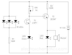
Description: The circuit utilizes the widely used Sharp IR module (the Vishay module can also be employed). The pin numbers indicated in the circuit are applicable to both the Sharp and Vishay modules. For other modules, it is advisable to consult their respective datasheets. The receiver features a 555 timer IC configured as an oscillator operating at approximately 38 kHz (functional within a range of 36 kHz to 40 kHz), which requires adjustment using a 10K preset. The receiver employs a Sharp IR module. When the IR beam from the transmitter strikes the IR module, the output is triggered, activating the relay, which deactivates when the beam is obstructed. The relay contacts can be utilized to turn alarms, lights, and other devices ON or OFF. The 10K preset should be calibrated until the receiver successfully detects the IR beam. This circuit can also function as a proximity sensor, detecting objects in front of the device without obstructing the IR beam. For this application, the LEDs should be directed in the same direction as the IR module and aligned at the same level. The recommended setup is illustrated in the circuit diagram. The LEDs should be adequately shielded with reflective materials such as glass or aluminum foil on the sides to prevent IR beam dispersion and ensure a focused beam. When unobstructed, the IR beam does not reflect onto the module, thus keeping the circuit inactive. When an object approaches the device, the IR light from the LEDs is reflected by the object onto the module, activating the circuit.
The circuit design centers around the integration of a Sharp IR module or an equivalent Vishay module, which serves as the core component for IR signal detection. The 555 timer IC is configured in astable mode to generate a pulse width modulation (PWM) signal at a frequency of approximately 38 kHz, which is optimal for IR communication. The frequency can be fine-tuned using a 10K potentiometer, allowing for precise adjustments to ensure reliable operation under varying environmental conditions.
The IR module acts as a receiver, capturing the emitted IR light from an IR LED transmitter. When the IR beam is unobstructed, the module remains inactive; however, when an object enters the detection range, the reflected IR light triggers the output of the module. This output is connected to a relay, which can control various loads, including alarms and lighting systems, providing versatility in application.
For proximity sensing applications, the circuit requires careful alignment of the IR LEDs and the IR module. The LEDs must be aimed in the same direction and positioned at the same height as the IR receiver to ensure effective reflection of the IR light. The use of reflective materials around the LEDs is crucial for concentrating the IR beam, enhancing the detection capability and reducing false activations caused by ambient light interference.
In summary, this circuit serves multiple functions, including remote control and proximity sensing, making it suitable for a variety of applications in automation and security systems. Proper calibration and alignment of components are essential for optimal performance and reliability.The circuit uses the very popular Sharp IR module (Vishay module can also be used). The pin nos. shown in the circuit are for the Sharp & VIshay modules. For other modules please refer to their respective datasheets. The receiver consists of a 555 timer IC working as an oscillator at about 38Khz (also works from 36kHz to 40kHz) which has to be adj usted using the 10K preset. The receiver uses a sharp IR module. When the IR beam from the transmitter falls on the IR module, the output is activated which activates the relay and de-activated when the beam is obstructed. The relay contacts can be used to turn ON/OFF alarms, lights etc. The 10K preset should be adjusted until the receiver detects the IR beam. The circuit can also be used as a proximity sensor, i. e to detect objects in front of the device without obstructing a IR beam. For this the LEDs should be pointed in the same direction as the IR module and at the same level. The suggested arrangement is shown in the circuit diagram. The LEDs should be properly covered with a reflective material like glass or aluminum foils on the sides to avoid the spreading of the IR beam and to get a sharp focus of the beam.
When there is nothing in front of them, the IR beam is not reflected onto the module and hence the circuit is not activated. When an object comes near the device, the IR light from the LEDs is reflected by the object onto the module and hence the circuit gets activated.
The circuit design centers around the integration of a Sharp IR module or an equivalent Vishay module, which serves as the core component for IR signal detection. The 555 timer IC is configured in astable mode to generate a pulse width modulation (PWM) signal at a frequency of approximately 38 kHz, which is optimal for IR communication. The frequency can be fine-tuned using a 10K potentiometer, allowing for precise adjustments to ensure reliable operation under varying environmental conditions.
The IR module acts as a receiver, capturing the emitted IR light from an IR LED transmitter. When the IR beam is unobstructed, the module remains inactive; however, when an object enters the detection range, the reflected IR light triggers the output of the module. This output is connected to a relay, which can control various loads, including alarms and lighting systems, providing versatility in application.
For proximity sensing applications, the circuit requires careful alignment of the IR LEDs and the IR module. The LEDs must be aimed in the same direction and positioned at the same height as the IR receiver to ensure effective reflection of the IR light. The use of reflective materials around the LEDs is crucial for concentrating the IR beam, enhancing the detection capability and reducing false activations caused by ambient light interference.
In summary, this circuit serves multiple functions, including remote control and proximity sensing, making it suitable for a variety of applications in automation and security systems. Proper calibration and alignment of components are essential for optimal performance and reliability.The circuit uses the very popular Sharp IR module (Vishay module can also be used). The pin nos. shown in the circuit are for the Sharp & VIshay modules. For other modules please refer to their respective datasheets. The receiver consists of a 555 timer IC working as an oscillator at about 38Khz (also works from 36kHz to 40kHz) which has to be adj usted using the 10K preset. The receiver uses a sharp IR module. When the IR beam from the transmitter falls on the IR module, the output is activated which activates the relay and de-activated when the beam is obstructed. The relay contacts can be used to turn ON/OFF alarms, lights etc. The 10K preset should be adjusted until the receiver detects the IR beam. The circuit can also be used as a proximity sensor, i. e to detect objects in front of the device without obstructing a IR beam. For this the LEDs should be pointed in the same direction as the IR module and at the same level. The suggested arrangement is shown in the circuit diagram. The LEDs should be properly covered with a reflective material like glass or aluminum foils on the sides to avoid the spreading of the IR beam and to get a sharp focus of the beam.
When there is nothing in front of them, the IR beam is not reflected onto the module and hence the circuit is not activated. When an object comes near the device, the IR light from the LEDs is reflected by the object onto the module and hence the circuit gets activated.
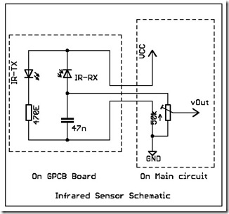
Circuit Diagram Of Simple Infrared Sensor Modules
The following circuit illustrates a simple infrared sensor module circuit diagram. Features include a simple infrared sensor module and flame detection.
The simple infrared sensor module circuit operates by utilizing an infrared (IR) transmitter and receiver pair. The IR transmitter emits...
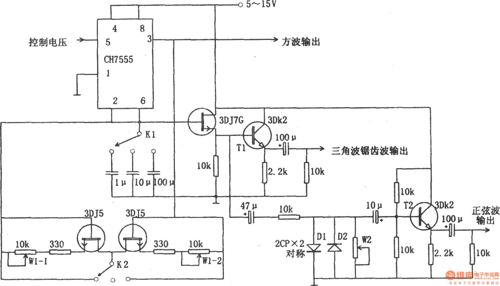
The function generator composed of 555 timer
The chart illustrates a function generator circuit utilizing a 555 timer. This circuit includes a CH7555 timer along with several transistors and RC components. It is capable of generating triangle waves, square waves, sine waves, sawtooth waves, and square wave...
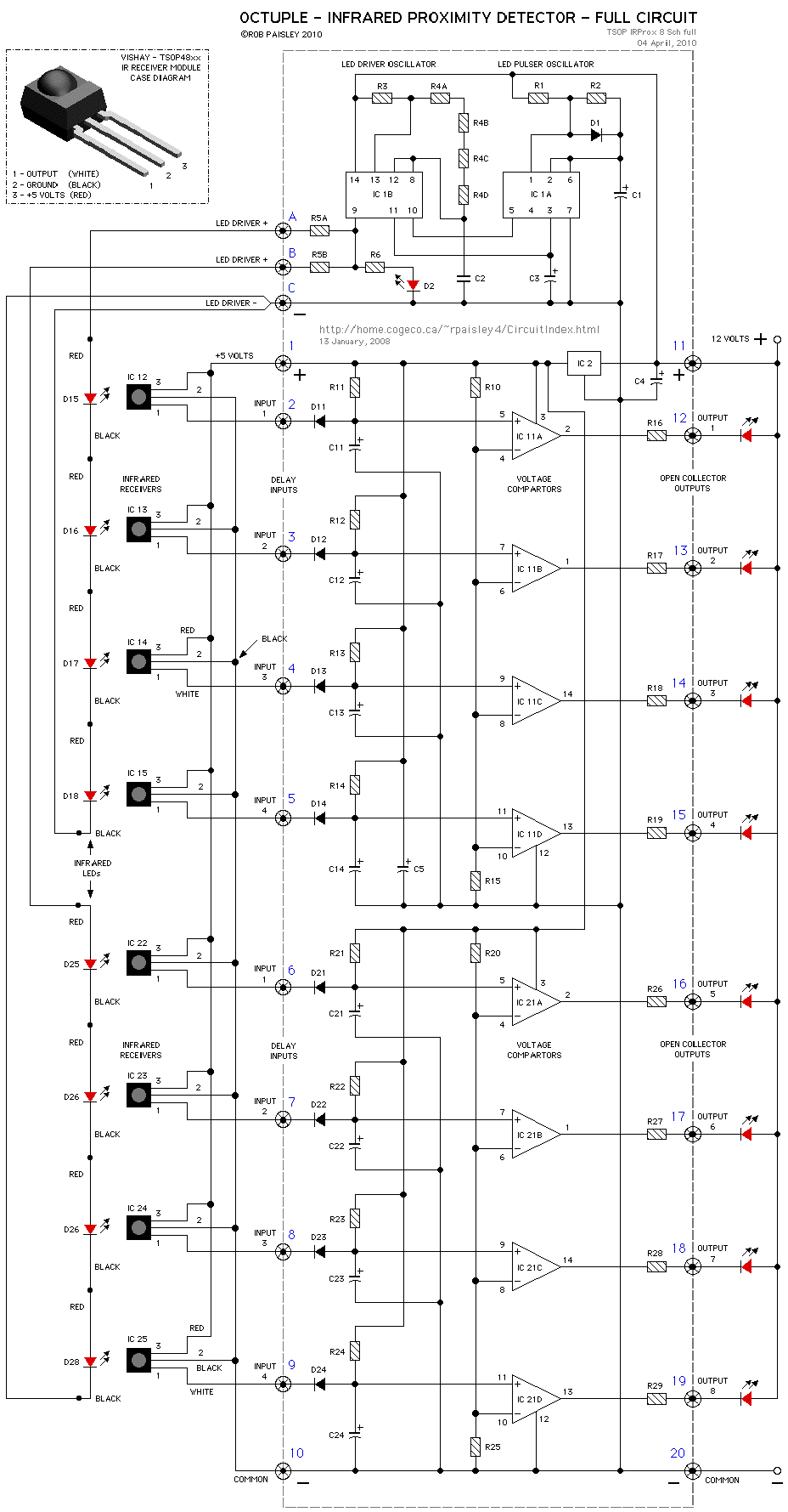
Infrared Proximity Detector circuit
The circuits on this page are for an Infrared Proximity Detector using the Vishay Electronics TSOP4830, which is an IR Receiver Module designed for remote control systems. The TSOP4830 functions as a sensitive infrared detector that operates without requiring shielding...
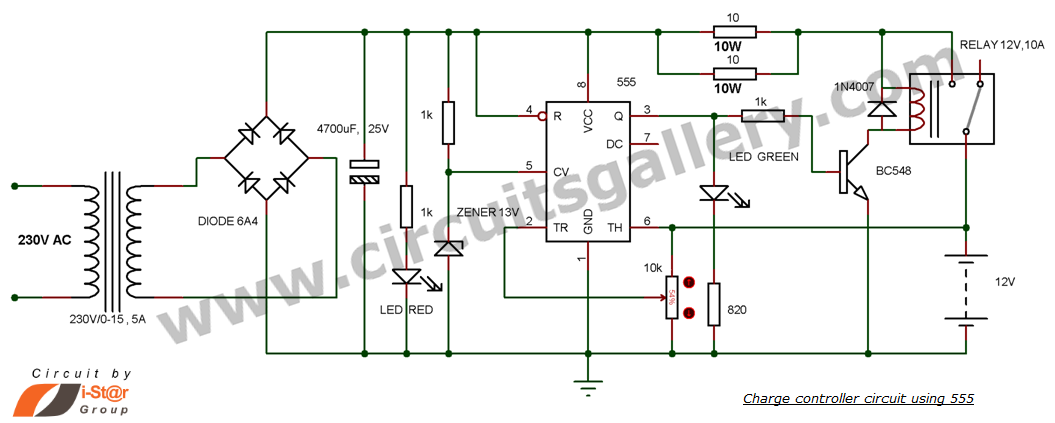
12v Battery Charger Circuit with Auto Cut off
This is a simple DIY charge controller schematic created in response to a request from one of the readers on our Facebook page. The primary component of this automatic battery charger circuit is a 555 timer, which compares the voltage...
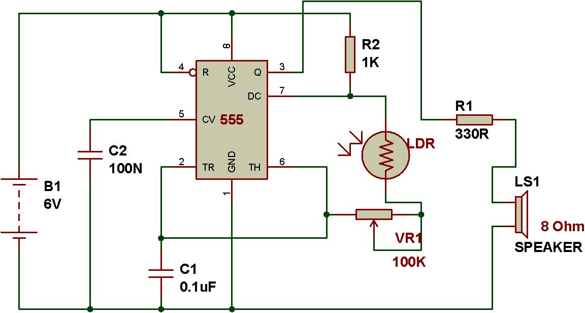
sound generator
The circuit described operates in astable mode using a 555 timer. Instead of a fixed resistor, a Light Dependent Resistor (LDR) is utilized to provide variable resistance for the 555 timer's operation in astable mode. As the resistance of the...
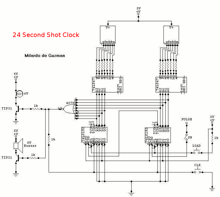
24 Second Shot Clocks
To initiate the process in 24 seconds, the LOAD switch and Reset switch must be pressed simultaneously. If this action is not performed, the countdown will commence from 99. A pulse input can be connected to a 555 astable multivibrator,...
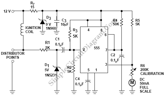
Car Tachometer with 555 IC
Pulses are received by the timer from the distributor points. When the timer output is high, Meter M receives a calibrated current through R6. The meter does not...
The circuit described involves a timer that receives pulse signals from distributor points,...
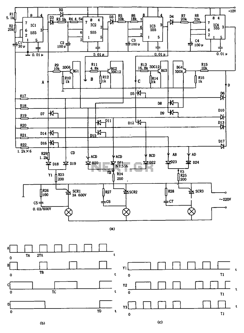
Advertising lights controller circuit diagram 555
The decorative lamp control circuit is illustrated in the figure. The controller comprises a pulse generator, a frequency divider, a matrix circuit, and a thyristor control circuit. Components IC1, R1, R2, C1, and others form a multivibrator where the oscillation...
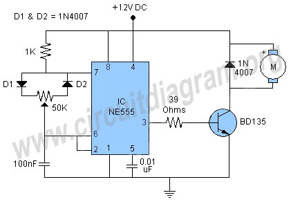
dc motor control pwm 555
This simple DC motor control or PWM circuit using a 555 IC can be utilized to regulate the speed of a DC motor. The circuit is straightforward and can be assembled quickly if all components are readily available.
The described circuit...