


Ion detector circuit diagram electronic project
#ion detector
#static electricity
#high voltage
#antenna
#sensitivity adjustment
#electronic project
#charge detection
#free ions
#leakage detection
#whip antenna
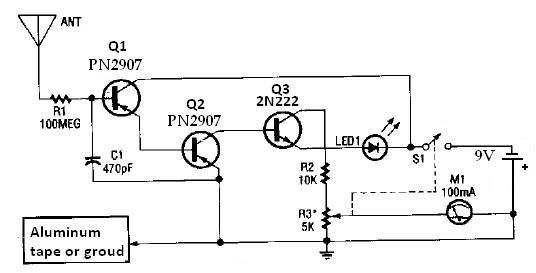
Description: This ion detector circuit is designed to sense static charges and free ions present in the air. It is capable of detecting the presence of free ions, static electricity, or high voltage leakage. The project utilizes a short whip antenna, and a resistor (R3) is incorporated to adjust the circuit's sensitivity. The circuit includes a micro-ammeter (M1) rated at 100 mA, which is configured to detect negative ions. To enable the detection of positive ions, one can simply reverse the polarity of the transistors within the circuit; this involves replacing PNP transistors with NPN transistors and vice versa.
This ion detector circuit operates on the principle of measuring ion concentration in the air, which can indicate the presence of static electricity or high voltage leakage. The short whip antenna serves as the primary sensing element, capturing free ions in the vicinity. The sensitivity of the circuit is adjustable via the resistor R3, allowing for fine-tuning based on the environmental conditions or specific detection requirements.
The micro-ammeter (M1), with a full-scale deflection of 100 mA, provides a visual representation of the ion concentration detected by the circuit. It is important to ensure that the meter is calibrated correctly to reflect accurate ion measurements. The configuration of the circuit is primarily focused on detecting negative ions; however, for applications requiring the detection of positive ions, the transistor configuration must be altered. This involves swapping the roles of PNP and NPN transistors, which changes the biasing conditions and allows the circuit to respond to positive ion charges.
The overall design is relatively straightforward, making it suitable for educational purposes or hobbyist projects. The simplicity of the circuit allows for easy troubleshooting and modifications, making it an excellent platform for understanding the principles of ion detection and static charge measurement. Care should be taken to ensure proper component ratings and connections to maintain circuit integrity and safety during operation.This ion detector circuit detects static charges and free ions in the air. This ion detector circuit can be used for detecting presence of free ions, static electricity or high voltage leakage. Antenna used in this project is a short whip antenna and the R3 resistor is used to adjust the sensitivity of the circuit.
The M1 from this circuit is a n 100mA micro-Ampere-meter. The detector is set up to detect negative ions. It can be made to detect positive ions by simply reversing the polarity of the transistors that comprise the circuit, i. e. , PNP units become NPN units, and NPN transistor is replaced by a PNP unit.
This ion detector circuit operates on the principle of measuring ion concentration in the air, which can indicate the presence of static electricity or high voltage leakage. The short whip antenna serves as the primary sensing element, capturing free ions in the vicinity. The sensitivity of the circuit is adjustable via the resistor R3, allowing for fine-tuning based on the environmental conditions or specific detection requirements.
The micro-ammeter (M1), with a full-scale deflection of 100 mA, provides a visual representation of the ion concentration detected by the circuit. It is important to ensure that the meter is calibrated correctly to reflect accurate ion measurements. The configuration of the circuit is primarily focused on detecting negative ions; however, for applications requiring the detection of positive ions, the transistor configuration must be altered. This involves swapping the roles of PNP and NPN transistors, which changes the biasing conditions and allows the circuit to respond to positive ion charges.
The overall design is relatively straightforward, making it suitable for educational purposes or hobbyist projects. The simplicity of the circuit allows for easy troubleshooting and modifications, making it an excellent platform for understanding the principles of ion detection and static charge measurement. Care should be taken to ensure proper component ratings and connections to maintain circuit integrity and safety during operation.This ion detector circuit detects static charges and free ions in the air. This ion detector circuit can be used for detecting presence of free ions, static electricity or high voltage leakage. Antenna used in this project is a short whip antenna and the R3 resistor is used to adjust the sensitivity of the circuit.
The M1 from this circuit is a n 100mA micro-Ampere-meter. The detector is set up to detect negative ions. It can be made to detect positive ions by simply reversing the polarity of the transistors that comprise the circuit, i. e. , PNP units become NPN units, and NPN transistor is replaced by a PNP unit.
Variable High Voltage Power Supply
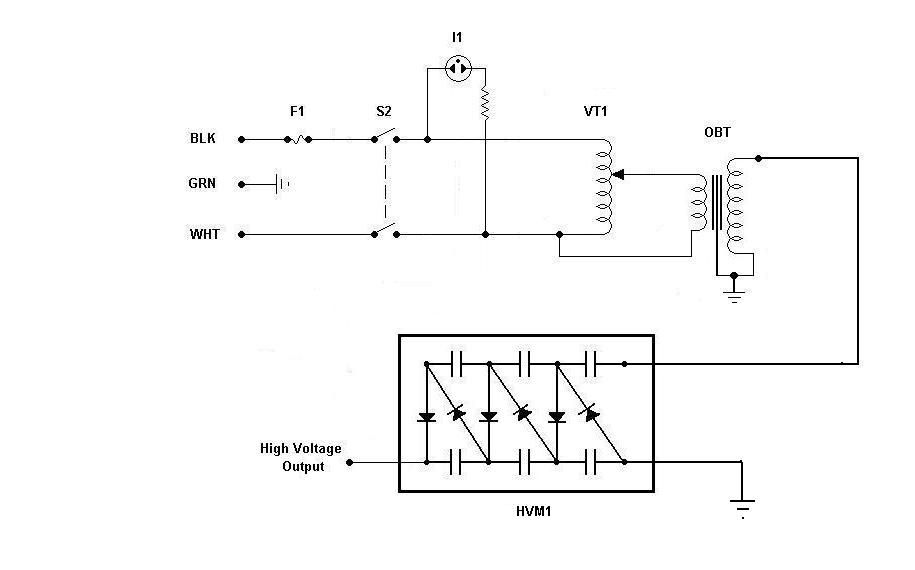
Using components from old microwave ovens, TV sets, and oil burners, it is possible to construct an economical instrument capable of producing high voltage outputs. The primary element in this setup is a voltage multiplier, which should be assembled first...
High Voltage Low Current Supply
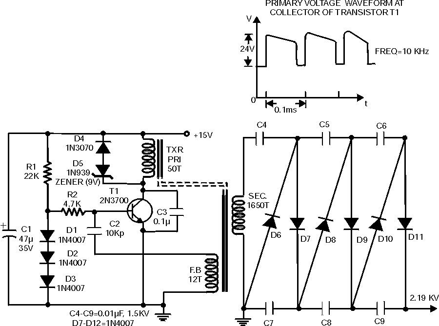
The following circuit illustrates a High Voltage, Low Current Supply. Features: This circuit is utilized for applications such as biasing gas-discharge tubes, radiation detectors, and similar devices.
The High Voltage, Low Current Supply circuit is designed to provide a stable high...
Low Cost High Voltage Power Supply
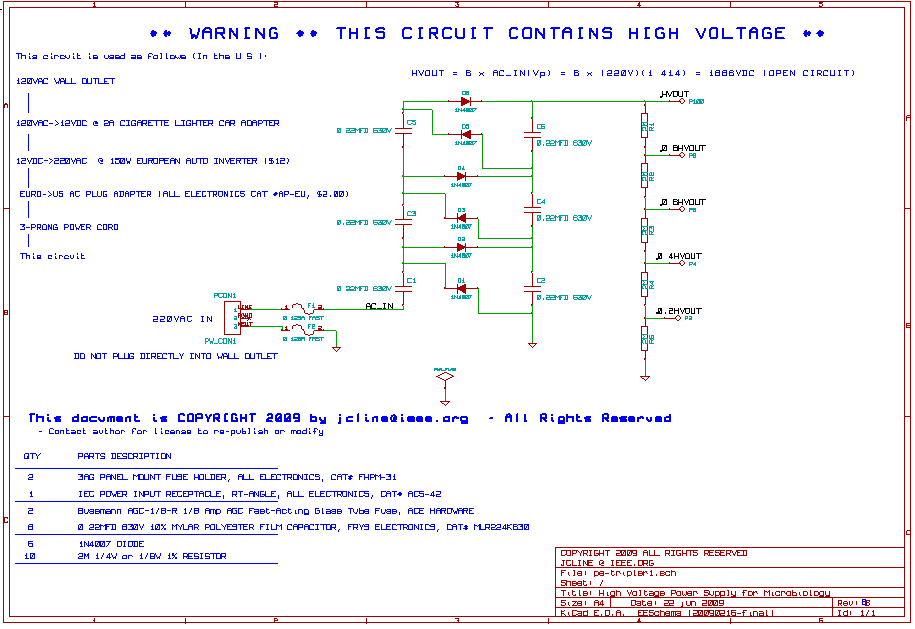
This high voltage, low current power supply has been designed for various experiments in systems and synthetic biology. The schematic and board layout are provided below. The circuit can output up to +1,866 VDC at under 1 mA and can...
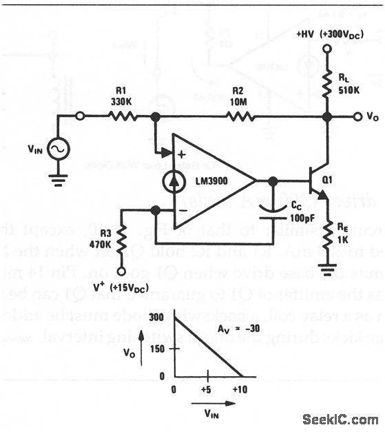
Norton high voltage inverting amplifier
This circuit is an inverting amplifier with an output voltage swing from approximately 0 to +300 V. Any transistor can be utilized for Q1, as long as the breakdown voltage exceeds 300 V (since the full high voltage will be...
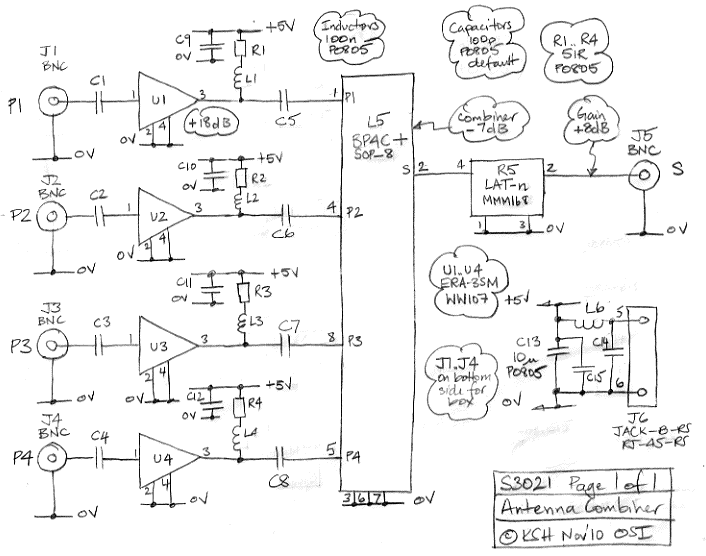
Antenna Combiner
The Antenna Combiner (A3021) is an active combiner designed to accommodate four 50-ohm coaxial antenna connections. It combines the signals from these four inputs, resulting in a net gain of approximately +11 dB. The A3021 is specifically intended for use...
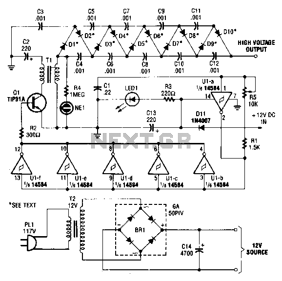
High-voltage-dc-generator
This circuit is powered by a 12-V DC power supply. The input to the circuit is amplified to generate a 10,000-V DC output. The output of the up-converter is subsequently directed into a 10-stage high-voltage multiplier to achieve a final...
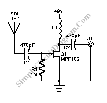
Antenna Booster for FM AM and SW Receiver
This AM/FM antenna booster circuit amplifies the broadband signal from the antenna. This antenna booster is designed to work for FM, AM, and SW receivers.
The AM/FM antenna booster circuit is an essential component for enhancing radio reception across various...
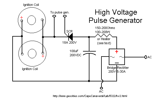
60kv ignition coil driver circuit
The ignition coil driver circuit described is a highly regarded design, reportedly created by Jochen Kronjaeger. It is intended to operate from a 230V source, although a modified version can function effectively at 120V. The circuit requires two ignition coils...
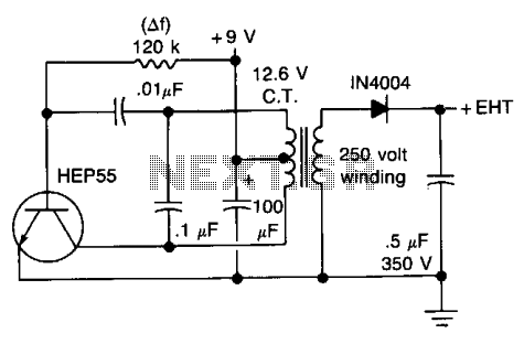
High voltage geiger counter supply
This circuit will generate approximately 300 volts DC at a very low current, sufficient for a GM tube. Caution is advised with the output.
The described circuit is a high-voltage DC power supply designed to provide approximately 300 volts, which is...