


Light Activated switch with Relay
#light activated
#relay
#photo resistor
#2N3904
#flip flop
#ambient lighting
#switch
#transistor
#sensor
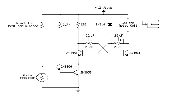
Description: This is same circuit as above with the addition of a photo resistor to trigger the flip flop instead of a push button. The bias resistor in series with photo resistor was chosen so that sufficient voltage is present at the base of the 2N3904 to supply current to the circuit in ambient lighting conditions. More: The circuit should toggle when the photo resistor is hit by a flashlight beam or other fast changing light source. Slow changes in light intensity will have no effect unless the light gets too bright to maintain sufficient bias for the 2N3904.
The described circuit utilizes a photoresistor (LDR) to control the operation of a flip-flop circuit, replacing a conventional push button switch. The flip-flop configuration allows for a bistable operation, meaning it can maintain its state until triggered again. The primary component utilized for the switching action is the 2N3904 NPN transistor, which acts as a driver for the flip-flop mechanism.
In this circuit, the photoresistor is connected in series with a bias resistor, which is crucial for establishing the appropriate voltage at the base of the 2N3904. The chosen bias resistor value is determined based on the expected ambient light conditions. Under normal lighting, the voltage at the base must be sufficient to turn on the transistor, allowing current to flow through the collector-emitter path and thus triggering the flip-flop.
When a sudden change in light intensity occurs—such as when a flashlight beam is directed at the photoresistor—the resistance of the LDR decreases significantly. This change allows a higher voltage to appear at the base of the 2N3904, switching it into saturation and enabling the toggle of the flip-flop state. Conversely, gradual changes in light intensity do not provide a sufficient voltage change to activate the transistor, ensuring that the circuit remains stable under fluctuating lighting conditions.
It is essential to consider the threshold at which the light intensity becomes too bright. If the light intensity exceeds a certain level, it could lead to a condition where the biasing of the 2N3904 is compromised, potentially causing erratic behavior in the circuit. Therefore, careful selection of the bias resistor and the characteristics of the photoresistor is vital to ensure reliable operation across varying lighting scenarios.
Overall, this circuit design demonstrates an innovative approach to using light as a control mechanism, enhancing the versatility of flip-flop circuits in applications where tactile switches may not be ideal.This is same circuit as above with the addition of a photo resistor to trigger the flip flop instead of a push button. The bias resistor in series with photo resistor was chosen so that sufficient voltage is present at the base of the 2N3904 to supply current to the circuit in ambient lighting conditions.
The circuit should toggle when the photo resistor is hit by a flashlight beam or other fast changing light source. Slow changes in light intensity will have no effect unless the light gets too bright to maintain sufficient bias for the 2N3904.
The described circuit utilizes a photoresistor (LDR) to control the operation of a flip-flop circuit, replacing a conventional push button switch. The flip-flop configuration allows for a bistable operation, meaning it can maintain its state until triggered again. The primary component utilized for the switching action is the 2N3904 NPN transistor, which acts as a driver for the flip-flop mechanism.
In this circuit, the photoresistor is connected in series with a bias resistor, which is crucial for establishing the appropriate voltage at the base of the 2N3904. The chosen bias resistor value is determined based on the expected ambient light conditions. Under normal lighting, the voltage at the base must be sufficient to turn on the transistor, allowing current to flow through the collector-emitter path and thus triggering the flip-flop.
When a sudden change in light intensity occurs—such as when a flashlight beam is directed at the photoresistor—the resistance of the LDR decreases significantly. This change allows a higher voltage to appear at the base of the 2N3904, switching it into saturation and enabling the toggle of the flip-flop state. Conversely, gradual changes in light intensity do not provide a sufficient voltage change to activate the transistor, ensuring that the circuit remains stable under fluctuating lighting conditions.
It is essential to consider the threshold at which the light intensity becomes too bright. If the light intensity exceeds a certain level, it could lead to a condition where the biasing of the 2N3904 is compromised, potentially causing erratic behavior in the circuit. Therefore, careful selection of the bias resistor and the characteristics of the photoresistor is vital to ensure reliable operation across varying lighting scenarios.
Overall, this circuit design demonstrates an innovative approach to using light as a control mechanism, enhancing the versatility of flip-flop circuits in applications where tactile switches may not be ideal.This is same circuit as above with the addition of a photo resistor to trigger the flip flop instead of a push button. The bias resistor in series with photo resistor was chosen so that sufficient voltage is present at the base of the 2N3904 to supply current to the circuit in ambient lighting conditions.
The circuit should toggle when the photo resistor is hit by a flashlight beam or other fast changing light source. Slow changes in light intensity will have no effect unless the light gets too bright to maintain sufficient bias for the 2N3904.
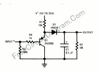
Single Transistor Half-Wave Peak Detector Circuit
Using only a single transistor and a few passive components, a fairly sensitive peak detector circuit can be built. This peak detector circuit is suitable for various applications.
The peak detector circuit utilizes a single transistor, typically configured in a common-emitter...
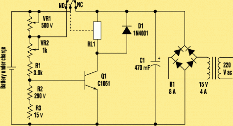
a single transistor smart battery charger
The electronic design features a smart battery charger schematic that utilizes only a single transistor. This design is notable as similar circuits typically employ simple integrated circuits. When the battery's charge level falls below a specific threshold voltage, the circuit...
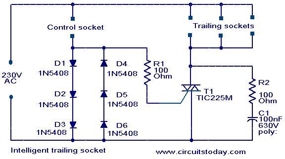
Intelligent trailing switch
This circuit is a straightforward yet effective design where devices connected to the trailing sockets will operate only when the device connected to the control socket is powered on. For instance, if a motor is connected to the control socket...
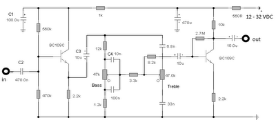
audio tone control 2 transistor circuit
The first BC109C transistor functions as a buffer, delivering a high input impedance of approximately 250k and exhibiting a voltage gain marginally below unity. Given that the Baxendall tone control circuit operates passively, it attenuates all audio frequencies. The audio...
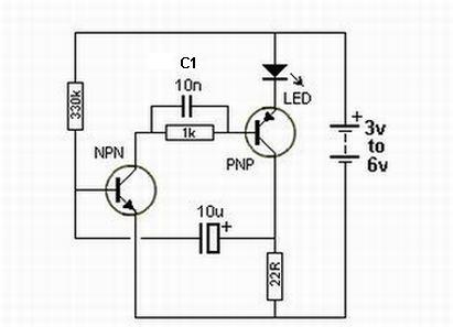
transistors Role of capacitor in this circuit
Oscillation is expected at the resonant frequency where the positive feedback is in phase with the input, specifically at 0 degrees. For oscillation to take place, the gain must be equal to or greater than 1 at that frequency. There...

Light Operated Relay Circuit
This light-sensitive circuit can operate a relay to switch on lamps or any AC loads when it detects darkness. It is ideal for use as a switchless night lamp.
The circuit utilizes a light-dependent resistor (LDR) as its primary sensing element....
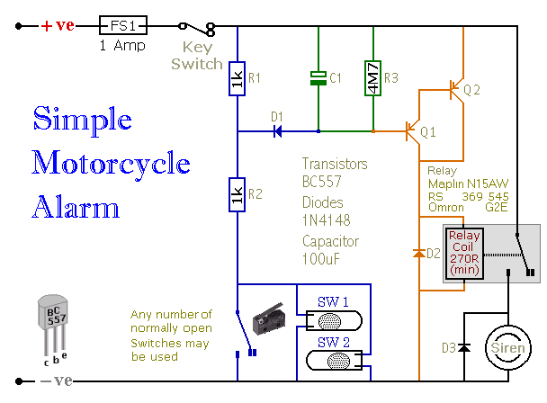
Simple Two-Transistor Motorcycle Alarm
When one of the switches is closed, the base of Q1 is connected to ground through D1 and R2. This activates Q1, which in turn activates Q2. Q2 connects the positive side of the relay coil to the supply line,...
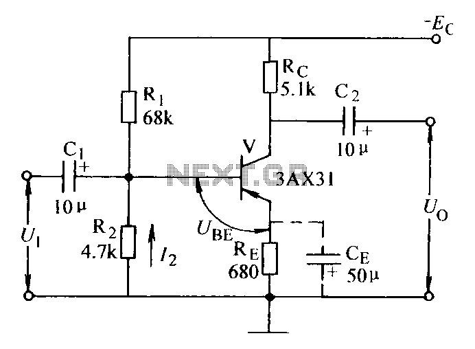
Current negative feedback voltage divider biasing circuit diagram
Current negative feedback voltage divider biased circuit diagram.
The current negative feedback voltage divider biased circuit is a configuration commonly used in electronic amplifiers to stabilize the operating point and improve linearity. This circuit typically consists of an amplifier, a voltage...
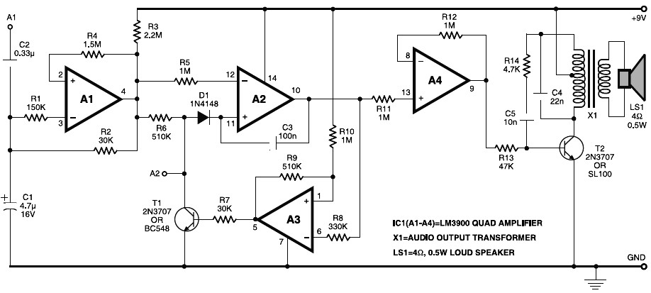
Electronic Horn
Electronic horn circuit diagram. When the power line is switched on, a basic tone is produced by transistor T2 and transformer X1, which is frequency-modulated by a wandering voltage generator affected by a low-frequency square wave generator. This is a...