


LM2940CT Sensor Connection
#LM2940CT
#sensor connection
#power dissipation
#storage temperature
#circuit diagram
#voltage regulation
#low dropout
#sensor interface
#electronic components
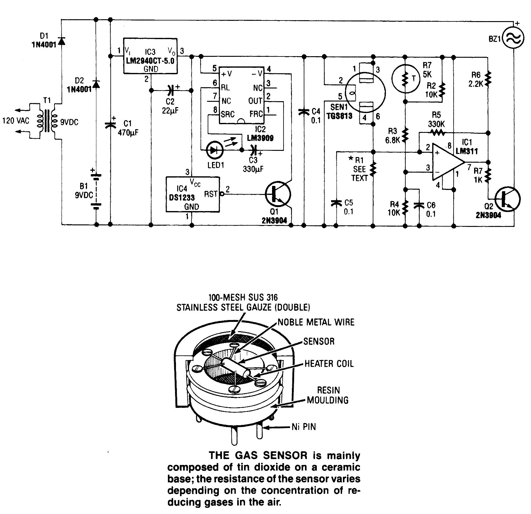
Description: The following circuit illustrates the LM2940CT sensor connection circuit diagram. Features include internal power dissipation and a storage temperature range.
The LM2940CT is a low dropout linear voltage regulator designed to provide a stable output voltage with a maximum dropout of 0.5V at up to 1A load current. This device is particularly suited for applications requiring a regulated voltage supply with minimal input-output voltage differential, making it ideal for battery-operated devices.
In the circuit diagram, the LM2940CT is typically connected to a power source, with input and output capacitors placed according to the manufacturer's recommendations to ensure stability and transient response. The input capacitor, often a 0.1µF ceramic capacitor, is connected close to the input pin to filter high-frequency noise. An additional larger electrolytic capacitor (e.g., 10µF to 100µF) may be added to enhance stability and transient response.
The output capacitor is crucial for maintaining the stability of the LM2940CT. A tantalum or aluminum electrolytic capacitor with a value of at least 22µF is usually connected at the output to ensure proper voltage regulation. The circuit may also include a diode for reverse polarity protection, ensuring that the regulator is safeguarded against incorrect connections.
The storage temperature range for the LM2940CT is typically between -40°C to +125°C, allowing it to operate effectively in a variety of environmental conditions. This feature is particularly beneficial in automotive and industrial applications where temperature fluctuations are common.
Overall, the LM2940CT sensor connection circuit is designed to provide reliable voltage regulation while ensuring protection and stability through appropriate component selection and placement.The following circuit shows about LM2940CT Sensor Connection Circuit Diagram. Features: Internal Power Dissipation, Storage Temperature Range ..
The LM2940CT is a low dropout linear voltage regulator designed to provide a stable output voltage with a maximum dropout of 0.5V at up to 1A load current. This device is particularly suited for applications requiring a regulated voltage supply with minimal input-output voltage differential, making it ideal for battery-operated devices.
In the circuit diagram, the LM2940CT is typically connected to a power source, with input and output capacitors placed according to the manufacturer's recommendations to ensure stability and transient response. The input capacitor, often a 0.1µF ceramic capacitor, is connected close to the input pin to filter high-frequency noise. An additional larger electrolytic capacitor (e.g., 10µF to 100µF) may be added to enhance stability and transient response.
The output capacitor is crucial for maintaining the stability of the LM2940CT. A tantalum or aluminum electrolytic capacitor with a value of at least 22µF is usually connected at the output to ensure proper voltage regulation. The circuit may also include a diode for reverse polarity protection, ensuring that the regulator is safeguarded against incorrect connections.
The storage temperature range for the LM2940CT is typically between -40°C to +125°C, allowing it to operate effectively in a variety of environmental conditions. This feature is particularly beneficial in automotive and industrial applications where temperature fluctuations are common.
Overall, the LM2940CT sensor connection circuit is designed to provide reliable voltage regulation while ensuring protection and stability through appropriate component selection and placement.The following circuit shows about LM2940CT Sensor Connection Circuit Diagram. Features: Internal Power Dissipation, Storage Temperature Range ..
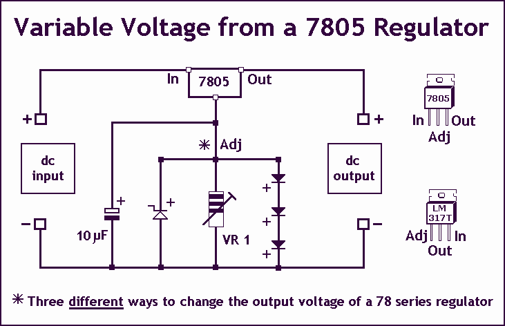
Variable Voltage Regulation
Controlling the output voltage from a regulator can be made variable in three ways:
1. Using a fixed reference zener diode to increase the output by the value of the zener
2. A variable resistor for variable output, note that...
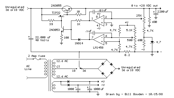
variable voltage and current power supply
An alternative method for utilizing operational amplifiers (op-amps) to regulate a power supply is illustrated below. The power transformer necessitates an additional winding to provide the op-amps with a bipolar voltage of +/- 8 volts. This negative voltage is also...
Voltage Regulators
Until Willow Garage was acquired, there was work as a Web Robotics Engineer. This title reflects a role as a full-stack engineer focused on real-time, distributed robot control. Notable projects include an XML-RPC server and client for Node.js, a deprecated...
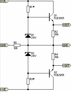
Simple Pre-Regulator
There will be many occasions when it is beneficial to utilize the P05 supply module sourced from a higher voltage supply. For instance, this could be advantageous when integrating balanced inputs.
The P05 supply module is designed to facilitate the conversion...
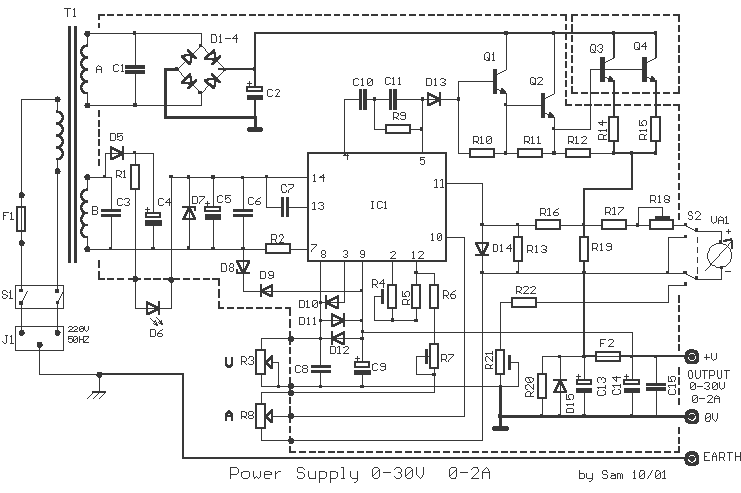
Power Supply 0-30V / 0-2A
The basic requirements for a laboratory power supply are to provide the necessary voltages and currents with low output resistance, low noise, minimal ripple, and good stabilization. These requirements are addressed within the circuit design. Many power supplies incorporate electronic...

psu
The Chameleon II Power Supply Circuits convert the raw input supply into stable voltage outputs necessary for the Chameleon interfaces. The outputs provided are +5V, +12V, and -12V.
The Chameleon II Power Supply Circuits are designed to ensure reliable operation of...
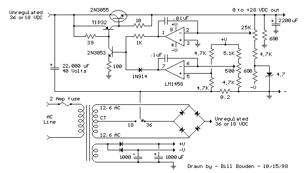
Current and Variable Voltage Power Supply
Another adjustment of application operational amplifiers to adapt a power supply is apparent below. The power supply requires an additional adjustment to supply the op-amps with a bipolar voltage (+/- 8 volts), and the negative voltage is also used to...
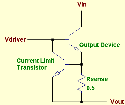
protected
A voltage regulator is designed to provide a fixed voltage to any load. This inherently means it must supply the necessary current through that load to satisfy Ohm's Law, I = V/R. As the resistance (R) approaches zero, such as...
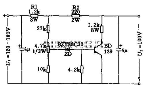
100v / 10ma regulator circuit
The circuit features no-load and short circuit protection mechanisms. To accommodate short circuit conditions, it is necessary to increase resistors R1 and R2 to allow for power dissipation; for example, R1 can be set to 1.2kΩ with a power rating...