


LM56 diagram of Circuit of the Thermostat project
#thermostat
#LM56
#temperature sensor
#electronic circuit
#low power
#IC
#voltage reference
#temperature control
#sensor circuit
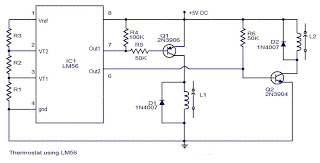
Description: The values of the LM56 thermostat project circuit diagram for resistors R1, R2, and R3 at the travel points VT1 and VT2 can be determined using the following equations. This electronic circuit thermostat with the IC LM56 serves as a simple project reference. The IC LM56 is a low-power, dual-output thermostat characterized by stable trip temperatures at two points, referred to as VT1 and VT2. These points are established by dividing the LM56's internal reference voltage of 1.250 volts using three external resistors (R1, R2, and R3). The LM56 IC features two digital outputs; output 1 becomes low when the temperature exceeds T1 and returns high when the temperature falls below (T1 ± Hysteresis). The IC LM56 includes several useful features, such as an internal voltage reference, an internal temperature sensor, and two internal voltage comparators.
The LM56 thermostat circuit is designed to regulate temperature by utilizing the IC's dual-output functionality. The circuit operates by monitoring the temperature through its internal sensor, which provides a reference for the temperature thresholds VT1 and VT2. The resistors R1, R2, and R3 are critical in setting these thresholds, as they form a voltage divider that allows for precise control over the trip points. The output behavior of the IC is defined by the temperature conditions: when the ambient temperature rises above the set point T1, output 1 transitions to a low state, indicating that cooling is required. Conversely, when the temperature drops below the set point, output 1 returns to a high state, signaling that the heating or cooling mechanism can be turned off.
The internal architecture of the LM56 includes two voltage comparators that compare the voltage from the internal temperature sensor against the reference voltage set by the resistors. This allows for accurate detection of temperature changes and ensures reliable operation. The hysteresis feature is essential for preventing rapid cycling of the outputs, which can occur if the temperature hovers around the set point. By implementing hysteresis, the circuit can maintain stable operation without unnecessary switching, thus enhancing the longevity of connected components.
Overall, the LM56 thermostat project circuit is a practical solution for temperature control applications, offering simplicity in design while incorporating essential features for effective performance. The use of external resistors allows for customization of the temperature set points, making it adaptable to various requirements.The values of LM56 Thermostat project Circuit diagram of R1, R2 and R3 for the points of travel, VT1 and VT2 can be determined using the subsequent equations. This thermostat of electronic circuit with IC LM56 diagram what simple project, you can use as reference.
As you know, IC LM56 is correct double output thermostat low power characterized by National Semiconductors. trip temperature stable 2 points called VT1 and VT2 are made with dividing the LM56 IC 1, 250 reference internal voltage volts by three outside resistors (R1, R2 and R3) component. There are 2 digital outputs for LM56 IC which is that output1 becomes weak when the temperature increases over T1 and goes high when the temperature decreases below (temperature T1 ±Hysteresis).
Component IC LM56 has a variety of useful features as internal voltage reference internal temperature sensor, 2 internal voltage comparators, etc.
The LM56 thermostat circuit is designed to regulate temperature by utilizing the IC's dual-output functionality. The circuit operates by monitoring the temperature through its internal sensor, which provides a reference for the temperature thresholds VT1 and VT2. The resistors R1, R2, and R3 are critical in setting these thresholds, as they form a voltage divider that allows for precise control over the trip points. The output behavior of the IC is defined by the temperature conditions: when the ambient temperature rises above the set point T1, output 1 transitions to a low state, indicating that cooling is required. Conversely, when the temperature drops below the set point, output 1 returns to a high state, signaling that the heating or cooling mechanism can be turned off.
The internal architecture of the LM56 includes two voltage comparators that compare the voltage from the internal temperature sensor against the reference voltage set by the resistors. This allows for accurate detection of temperature changes and ensures reliable operation. The hysteresis feature is essential for preventing rapid cycling of the outputs, which can occur if the temperature hovers around the set point. By implementing hysteresis, the circuit can maintain stable operation without unnecessary switching, thus enhancing the longevity of connected components.
Overall, the LM56 thermostat project circuit is a practical solution for temperature control applications, offering simplicity in design while incorporating essential features for effective performance. The use of external resistors allows for customization of the temperature set points, making it adaptable to various requirements.The values of LM56 Thermostat project Circuit diagram of R1, R2 and R3 for the points of travel, VT1 and VT2 can be determined using the subsequent equations. This thermostat of electronic circuit with IC LM56 diagram what simple project, you can use as reference.
As you know, IC LM56 is correct double output thermostat low power characterized by National Semiconductors. trip temperature stable 2 points called VT1 and VT2 are made with dividing the LM56 IC 1, 250 reference internal voltage volts by three outside resistors (R1, R2 and R3) component. There are 2 digital outputs for LM56 IC which is that output1 becomes weak when the temperature increases over T1 and goes high when the temperature decreases below (temperature T1 ±Hysteresis).
Component IC LM56 has a variety of useful features as internal voltage reference internal temperature sensor, 2 internal voltage comparators, etc.
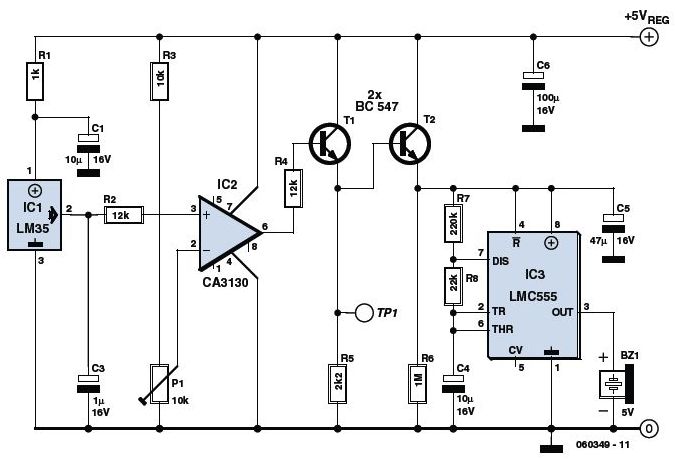
Overheat Detector Alarm Switch
The circuit utilizes a precision integrated temperature sensor, the LM35 (IC1), which provides a linear and directly proportional output in millivolts over a temperature range of 0 to +155 degrees Celsius. This sensor can be incorporated into fire smoke detectors,...

Two-Wire Temperature Sensor
Remote temperature measurements must be connected to the relevant test instrument using a cable. Typically, a three-core cable is employed: one core for the signal and two for the power supply. If a two-core cable is necessary, one of the...
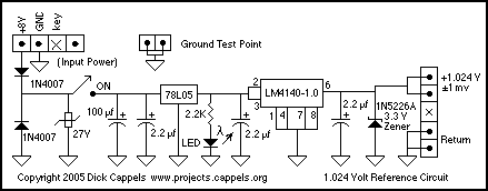
Voltage Reference LED indicator
A keyed power input connector, series rectifier and a shunt rectifier, both 1N4007, prevent reverse voltage from being applied to the power input. A 27 volt metal oxide varistor clamps the voltage to the 78L05 that follow it, to less...
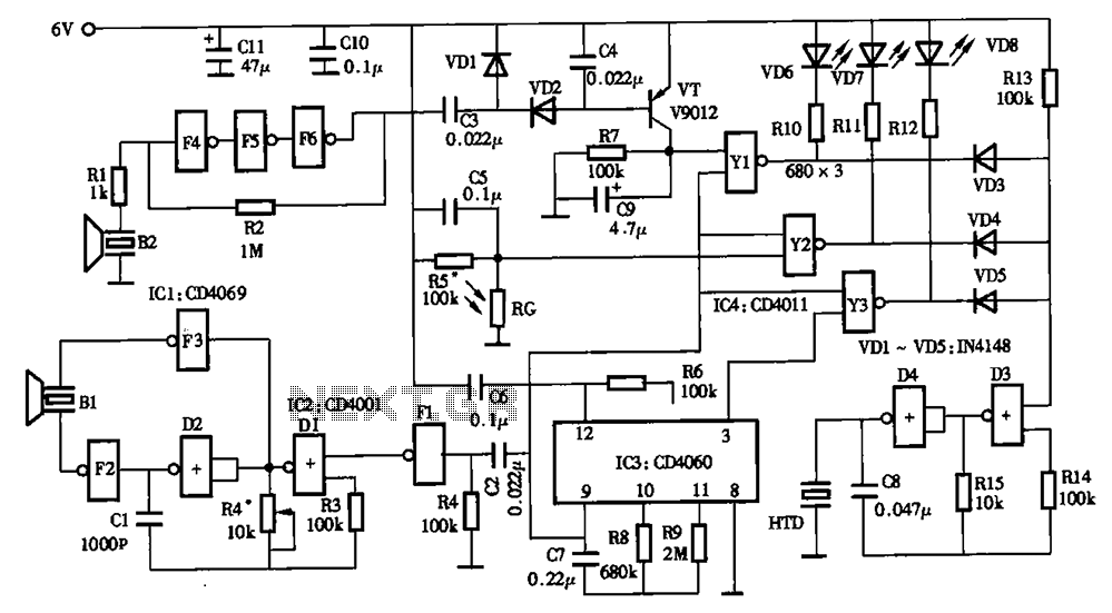
Low power timer switch
The timing circuit utilizes an electronic switch composed of F1, F2, and VT1 to reduce quiescent current to approximately 1 to 2 A with the 555 timer. Upon initial power-up, the voltage across capacitor C2 cannot instantly change, causing the...
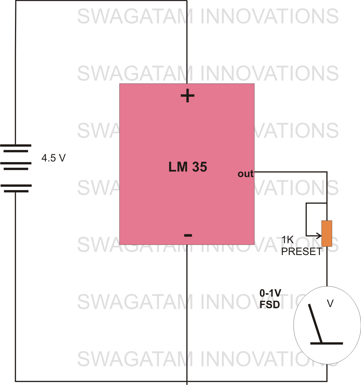
making simplest room thermometer
The circuit diagram provided illustrates a straightforward setup. There is no requirement for complex circuitry; simply connect a 0-1 V full-scale deflection (FSD) moving coil meter across the designated pins of the integrated circuit (IC). Adjust the potentiometer as needed,...
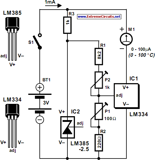
Celsius Thermometer
The circuit for the Celsius thermometer depicted in the diagram is based on the well-known LM334 type from National Semiconductor. This integrated circuit (IC) functions as a sensor that outputs a current directly proportional to the temperature in Kelvin (K)....

Temperature Relay Circuit
This is a circuit design for a temperature relay that can be used to signal a fire or monitor temperature set points. The adjustment of P1 is necessary to ensure that the base voltage of T1 is 0.5V lower than...
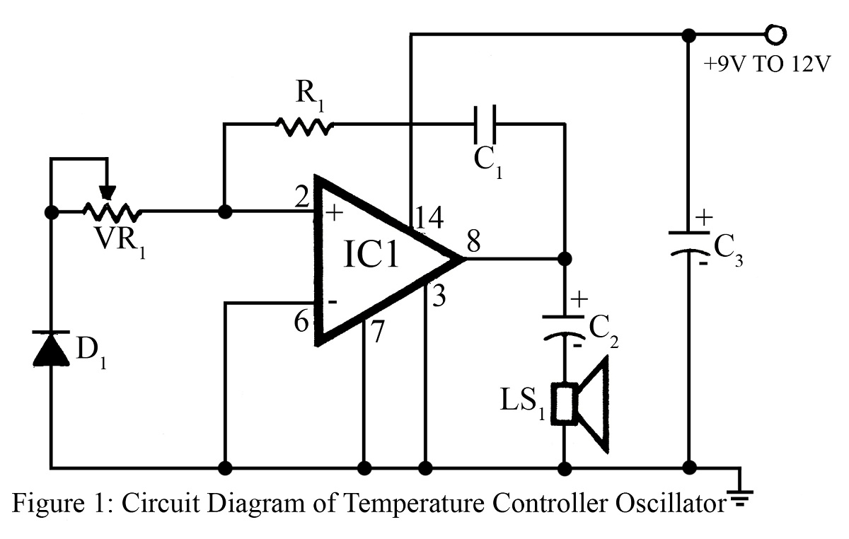
Temperature controlled oscillator
The output frequency or tone of this oscillator circuit varies with the temperature at which the input germanium diode is maintained. The reverse resistance of D1 ranges from 500 ohms to 10 k ohms when the temperature fluctuates between 20°C...
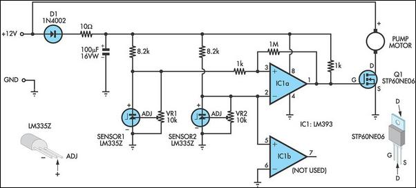
Pump Controller For Solar Hot Water System
This circuit optimizes the operation of a solar hot water system. When the water in the solar collector is hotter than the storage tank, the pump runs. The circuit comprises two LM335Z temperature sensors, a comparator, and a MOSFET. Sensor...