


Photo interrupter circuit diagram
#photo interrupter
#phototransistor
#electromagnet
#light sensor
#circuit diagram
#dark state
#current flow
#sensor circuit
#optical sensor
#trigger mechanism
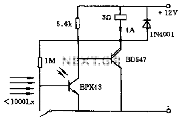
Description: In the circuit's resting (dark) state, current flows through the electromagnet M. When light shines on the phototransistor, it turns on, causing the final stage transistor to enter the OFF state, which releases the solenoid. A 1M ohm feedback to the photosensitive base of the transistor ensures that even when light is absent, the time-sensitive transistor remains activated. The system resets to its initial state by pressing the reset button T. A Darlington transistor can be utilized in place of an amplifier for greater magnification.
The described circuit operates on a principle of light sensitivity and feedback control. Initially, in the dark state, the electromagnet M is energized, allowing a current to flow that keeps the system in a ready state. The phototransistor acts as a light sensor; when illuminated, it activates, which subsequently deactivates the final stage transistor. This deactivation results in the solenoid being released, indicating a change in the circuit state from active to inactive.
The inclusion of a 1M ohm feedback resistor plays a crucial role in maintaining the transistor’s state. This feedback mechanism allows the circuit to retain its activated state even after the light source is removed. The time-sensitive nature of the transistor is critical for ensuring that the circuit remains responsive to transient changes in light conditions.
The reset mechanism is straightforward; pressing the reset button T reverts the circuit back to its original state, allowing for repeated operation. This functionality is essential for applications where the circuit needs to be reset frequently without manual intervention in the light detection process.
Furthermore, the option to use a Darlington transistor as an amplifier enhances the circuit's performance by providing a higher current gain. This characteristic is particularly beneficial in applications requiring substantial amplification of the input signal from the phototransistor, thereby improving overall sensitivity and responsiveness of the circuit.
Overall, this circuit design effectively integrates phototransistor operation, feedback mechanisms, and amplification to create a versatile system suitable for various electronic applications. Circuit at rest (dark) state operation the electromagnet M current flows, once there is sufficient strength so that light shines on the phototransistor is turned on, that is th e final stage transistor is in the OFF state, the solenoid release. Because by 1M ohm feedback to the photosensitive base of the transistor effect, so that even light cancel time-sensitive transistor is still turned on. Until press the reset button T, in order to return to the initial state. Darlington transistor which can be used in place of an amplifier greater magnification.
The described circuit operates on a principle of light sensitivity and feedback control. Initially, in the dark state, the electromagnet M is energized, allowing a current to flow that keeps the system in a ready state. The phototransistor acts as a light sensor; when illuminated, it activates, which subsequently deactivates the final stage transistor. This deactivation results in the solenoid being released, indicating a change in the circuit state from active to inactive.
The inclusion of a 1M ohm feedback resistor plays a crucial role in maintaining the transistor’s state. This feedback mechanism allows the circuit to retain its activated state even after the light source is removed. The time-sensitive nature of the transistor is critical for ensuring that the circuit remains responsive to transient changes in light conditions.
The reset mechanism is straightforward; pressing the reset button T reverts the circuit back to its original state, allowing for repeated operation. This functionality is essential for applications where the circuit needs to be reset frequently without manual intervention in the light detection process.
Furthermore, the option to use a Darlington transistor as an amplifier enhances the circuit's performance by providing a higher current gain. This characteristic is particularly beneficial in applications requiring substantial amplification of the input signal from the phototransistor, thereby improving overall sensitivity and responsiveness of the circuit.
Overall, this circuit design effectively integrates phototransistor operation, feedback mechanisms, and amplification to create a versatile system suitable for various electronic applications. Circuit at rest (dark) state operation the electromagnet M current flows, once there is sufficient strength so that light shines on the phototransistor is turned on, that is th e final stage transistor is in the OFF state, the solenoid release. Because by 1M ohm feedback to the photosensitive base of the transistor effect, so that even light cancel time-sensitive transistor is still turned on. Until press the reset button T, in order to return to the initial state. Darlington transistor which can be used in place of an amplifier greater magnification.
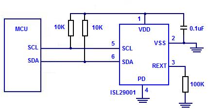
Digital Light Sensor
The Intersil ISL29001 is a digital light sensor designed to measure light intensity and easily interface with a microcontroller.
The Intersil ISL29001 is a highly integrated digital light sensor that operates using a photodiode and an analog-to-digital converter (ADC) to provide...
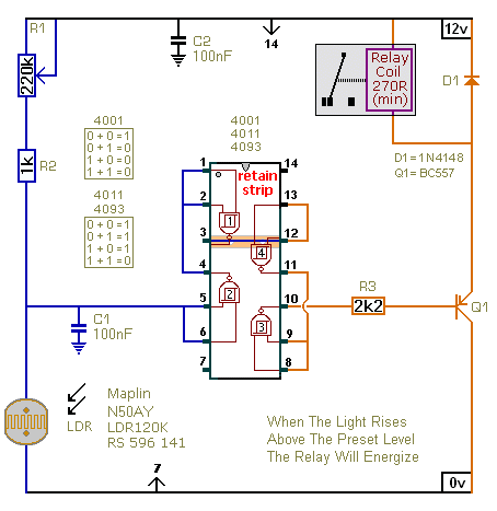
Light Controlled Relays
The first circuit energizes the relay when the light rises above the preset level. The second circuit energizes the relay when the light falls below the preset level. The two circuits are practically identical. The only difference between them is...
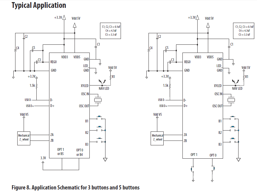
pcb Help identifying and finding shematics/datasheets for circuit board
The chip in the center with small bullet holes is likely proprietary. It is possible to salvage a few components from it, although understanding the circuit is not necessary for this purpose. Additionally, it is confirmed that the device is...
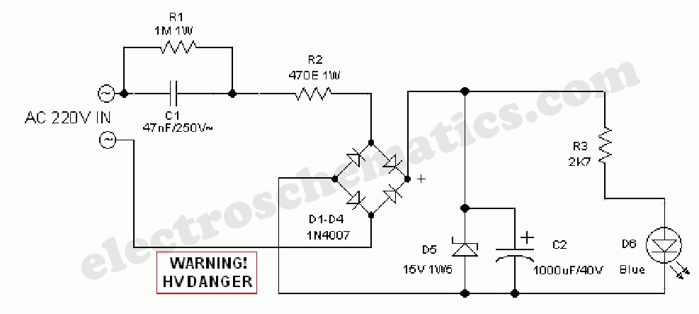
Automatic Night Lamp with Morning Alarm
This circuit project automatically activates a night lamp when the bedroom light is turned off. The lamp stays illuminated until the light sensor detects daylight.
The circuit operates using a light-dependent resistor (LDR) as the primary sensor to detect ambient light...

light sensor circuit using pic16c63
This light sensor circuit, utilizing a photosensor, serves as a bridge between light and electronics. It is constructed using an operational amplifier and the PIC16C63 microcontroller to control the sensor. While the circuit is not intended for precision applications, it...
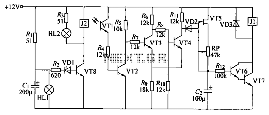
Blocking material monitoring circuit
A blocking material monitoring circuit is presented. When the optical path is obstructed by the material, the phototransistor VT1 turns off, which subsequently turns off transistors VT2, VT3, and VT4. This arrangement is coupled to a flip-flop configuration. When the...
Light Controlled Relays
The first circuit energizes the relay when the light rises above the preset level. The second circuit energizes the relay when the light falls below the preset level. The two circuits are practically identical. The only difference between them is...
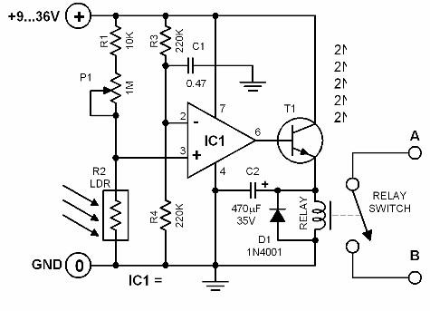
light activated switch
The brightness of the surrounding light controls the function of this circuit. The light sensor used in this circuit is a light-dependent resistor (LDR). This LDR is connected to the non-inverting input of the 741 op-amp IC. Once the intensity...
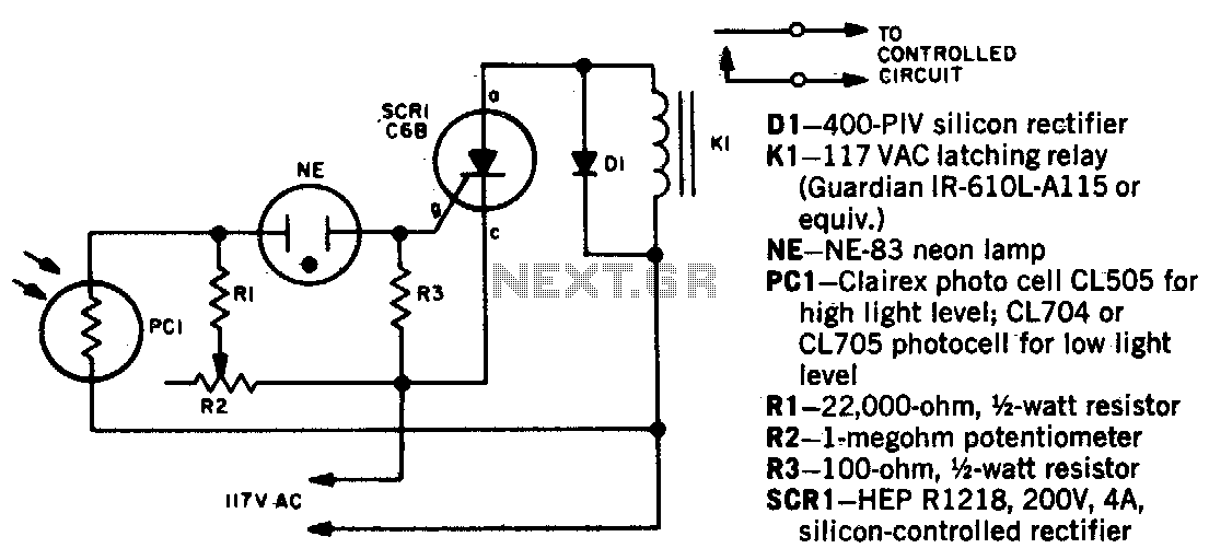
Light beam operated on-off relay
When a beam of light strikes the photocell, the voltage across the neon lamp NE-1 rises sharply. NE-1 turns on and triggers the SCR. K1 is an impulse relay whose contacts remain in position even after the coil current is...