


Proximity Switch Circuit Composed Of Integrated Magnetic Sensor HMC1001
#HMC1001
#magnetic sensor
#operational amplifier
#comparator
#proximity switch
#LED
#voltage output
#magnet detection
#sensor circuit

Description: The image depicts a proximity switch circuit that includes the HMC1001 Hall effect sensor, an operational amplifier (AMP04), and a light-emitting diode (LED). In this configuration, the operational amplifier functions as a comparator. When a magnet with a length of approximately 6mm to 12mm is brought close to the HMC1001, the output voltage of the MR electric bridge will change to around 30mV at a specific position.
The proximity switch circuit operates through the integration of the HMC1001 Hall effect sensor, which detects the presence of a magnetic field. The sensor generates a small voltage output proportional to the magnetic flux density it experiences. In this setup, when a magnet is brought within the effective range of the HMC1001, the sensor detects the magnetic field and produces a corresponding output voltage.
The operational amplifier (AMP04) is configured as a comparator to process the output signal from the HMC1001. This comparator compares the sensor's output voltage against a pre-defined reference voltage. When the output voltage from the HMC1001 exceeds this reference level, the operational amplifier switches its output state. This transition can be used to drive the LED, indicating the presence of the magnetic field.
The LED serves as a visual indicator of the sensor's activation, illuminating when the magnet is within the specified range. The circuit design allows for a simple yet effective method of detecting magnetic proximity, making it suitable for applications such as object detection, security systems, and automation tasks.
The overall design ensures that the circuit remains compact and efficient, with the HMC1001 providing sensitive detection capabilities and the AMP04 enabling precise signal processing. The choice of components allows for reliable operation in various environments, making it a versatile solution for proximity sensing applications.The picture shows the proximity switch circuit composed of the HMC1001 and operational amplifier (AMP04) and light emitting diode (LED). The operational amplifier is used as a comparator here. If taking a magnet with length about 6mm~12mm to close to the HMC1001, when it moves to a certain position, the MR electric bridge`s output voltage would be 30mV to..
The proximity switch circuit operates through the integration of the HMC1001 Hall effect sensor, which detects the presence of a magnetic field. The sensor generates a small voltage output proportional to the magnetic flux density it experiences. In this setup, when a magnet is brought within the effective range of the HMC1001, the sensor detects the magnetic field and produces a corresponding output voltage.
The operational amplifier (AMP04) is configured as a comparator to process the output signal from the HMC1001. This comparator compares the sensor's output voltage against a pre-defined reference voltage. When the output voltage from the HMC1001 exceeds this reference level, the operational amplifier switches its output state. This transition can be used to drive the LED, indicating the presence of the magnetic field.
The LED serves as a visual indicator of the sensor's activation, illuminating when the magnet is within the specified range. The circuit design allows for a simple yet effective method of detecting magnetic proximity, making it suitable for applications such as object detection, security systems, and automation tasks.
The overall design ensures that the circuit remains compact and efficient, with the HMC1001 providing sensitive detection capabilities and the AMP04 enabling precise signal processing. The choice of components allows for reliable operation in various environments, making it a versatile solution for proximity sensing applications.The picture shows the proximity switch circuit composed of the HMC1001 and operational amplifier (AMP04) and light emitting diode (LED). The operational amplifier is used as a comparator here. If taking a magnet with length about 6mm~12mm to close to the HMC1001, when it moves to a certain position, the MR electric bridge`s output voltage would be 30mV to..
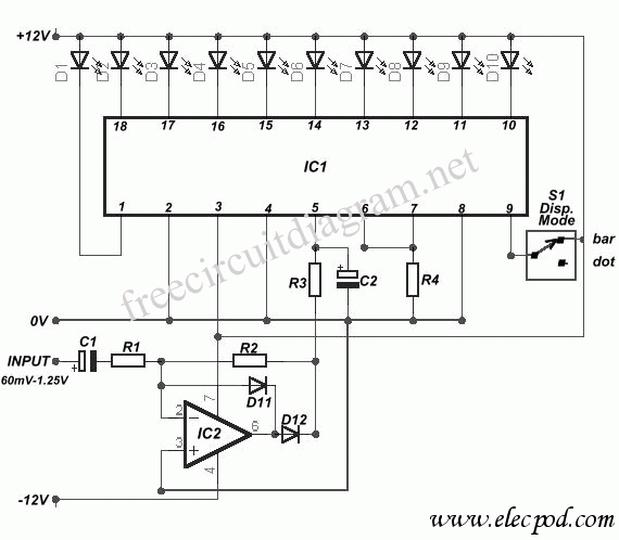
10 led VU Meter using LM3915
The circuit diagram represents a straightforward circuit-level indication featuring 10 LEDs. It utilizes a series of half-wave rectification controlled by the precision operational amplifier IC2 TL071. The LM3915 integrated circuit is employed to manage the LEDs, functioning as a VU...
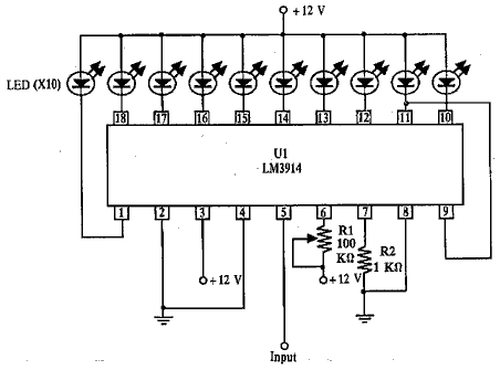
LED voltmeter schematic needed
A simple LED-based voltmeter is required to monitor the voltage of a variable power supply.
The proposed LED voltmeter circuit utilizes a series of light-emitting diodes (LEDs) to visually represent the voltage level of a variable power supply. This circuit...
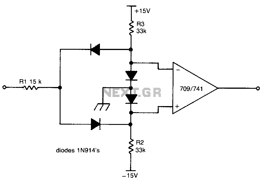
Dual limit comparator
This circuit provides a positive output when the input voltage exceeds 8 volts. Within these limits, the output remains negative. The threshold for the positive output is set by the ratio of resistors R1 and R2, while the threshold for...
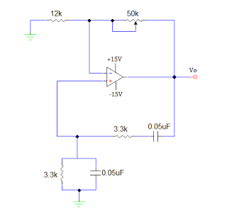
OP AMP SINE WAVE GENERATOR CIRCUIT
An operational amplifier-based sine wave generator circuit, commonly known as a Wien bridge oscillator, is recognized for its simplicity and stability. The Wien bridge oscillator connects the Wien bridge circuit between the amplifier's input and output terminals. The bridge features...
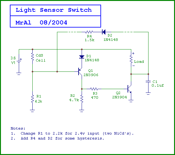
Light detector switch
Is there a way to automatically turn on an LED when it gets dark? A version was created using a relay and photoresistor that functioned properly, but concerns arose regarding potential battery drain. The project aims to integrate with a...
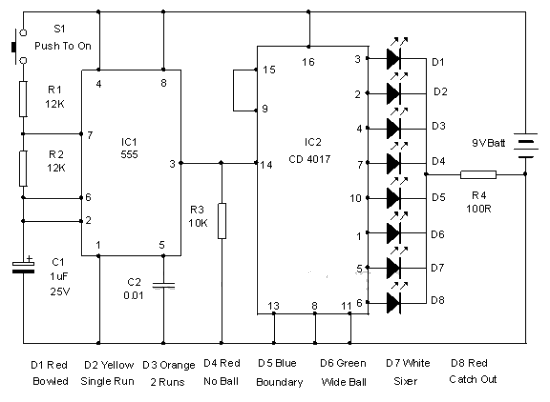
Electronic Cricket Match Game
This electronic cricket device is a gift for children. This simple battery-powered circuit can be used to simulate a cricket match with friends. Each LED in the circuit represents various statuses of the cricket match, such as a six, run...

LED
This series of light switches operates differently from traditional voltage-based systems. These light switches can function directly on the AC power network. The primary components utilized in this circuit are a TRIAC and a Light Dependent Resistor (LDR). The circuit...
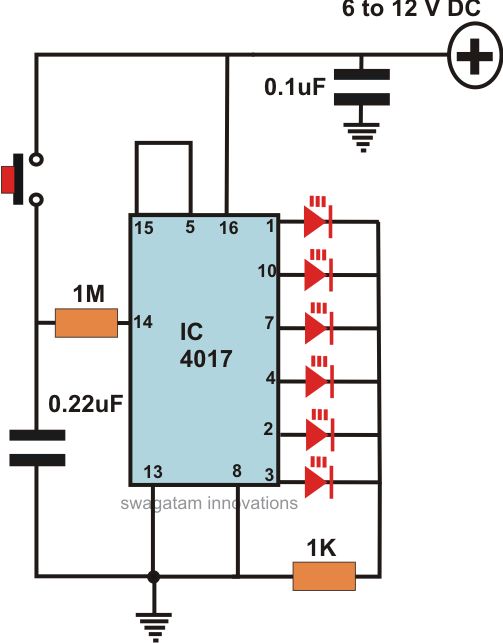
how to build a simple led light chaser circuit
This article offers a circuit diagram and a discussion on CMOS logic and IC layout for creating a set of attention-getting LED running lights. It details a simple sequential LED flasher or light chaser that can be built, including the...
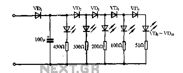
A passive light emitting diode output level indication circuit
A passive light-emitting diode output level indication circuit.
This circuit utilizes a light-emitting diode (LED) to provide a visual indication of the output level from a given source. The design is characterized by its passive nature, meaning it does not require...