


Proximity switch integrated circuit composed of the magnetic field sensor HMC1001
#magnetic field sensor
#HMC1001
#operational amplifier
#AMP04
#proximity switch
#LED
#circuit
#sensor integration
#signal amplification
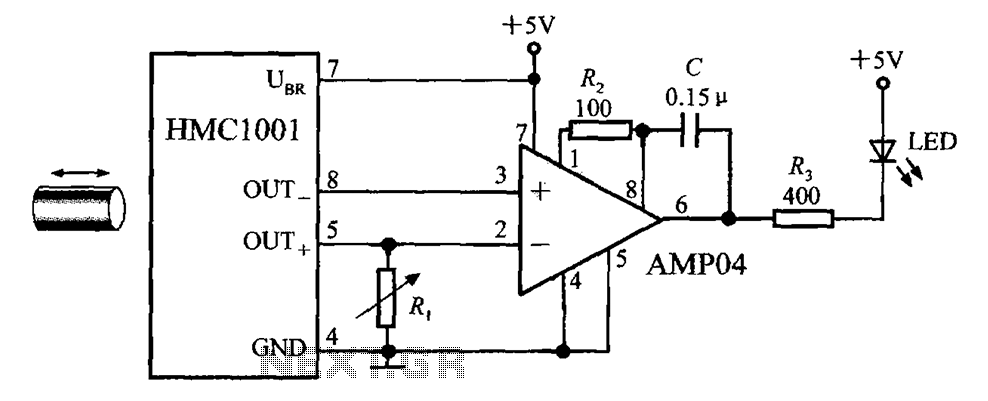
Description: The circuit depicted in the figure includes the HMC1001 magnetic sensor, an operational amplifier (AMP04), and a light-emitting diode (LED), forming a proximity switch circuit. In this application, the operational amplifier functions as a comparator. When a magnet, approximately 6mm to 12mm in length, is brought close to the HMC1001, the output voltage of the MR bridge reaches 30mV, causing the comparator to flip and the output to go low, which in turn illuminates the LED. Conversely, when the magnet is removed, the comparator output switches to a high level, turning off the LED. This circuit effectively operates as a proximity switch with an indicator light, suitable for detecting displacement, speed, and other non-electrical variables. The threshold voltage of the switch can be adjusted by modifying the value of resistor R1.
The proximity switch circuit integrates several key components to achieve its functionality. The HMC1001 is a magnetic sensor that detects the presence of a magnetic field. When a magnet approaches the sensor, it generates a voltage output that is fed into the operational amplifier, which is configured as a comparator. The comparator compares the sensor output voltage to a preset reference voltage.
The operational amplifier (AMP04) is chosen for its precision and ability to operate in low-voltage scenarios. The output of the comparator is connected to the anode of the LED, while the cathode is connected to ground through a current-limiting resistor. This configuration ensures that the LED only activates when the output of the comparator is low, indicating the presence of the magnet.
Resistor R1 plays a crucial role in setting the reference voltage for the comparator. By adjusting R1, the sensitivity of the circuit can be fine-tuned, allowing it to respond to different strengths of magnetic fields. This feature makes the circuit versatile for various applications, including proximity sensing in automation systems, speed detection in moving objects, and other non-contact measurements.
The overall design of this proximity switch circuit is compact and efficient, making it suitable for integration into various electronic systems where space and power consumption are critical considerations. The use of an LED as an indicator provides immediate visual feedback, enhancing the usability of the circuit in practical applications. As shown in FIG grounds HMC1001 and an operational amplifier (AMP04) and light emitting diode (LED) constituting the proximity switch circuit. As used herein, the op amp as a c omparator. The length of about 6mm ~ 12mm magnet closer HMC1001, when moved to a certain position, MR bridge output voltage reaches 30mV, the comparator flip, output goes low the LED light. If the magnet is removed, the comparator outputs a high level so that the LED goes out. Obviously, this circuit is equivalent to a proximity switch with indicator light can be used to detect displacement, speed and other non-electricity.
Adjusting the value of the resistor R1 can set the threshold voltage of the switch.
The proximity switch circuit integrates several key components to achieve its functionality. The HMC1001 is a magnetic sensor that detects the presence of a magnetic field. When a magnet approaches the sensor, it generates a voltage output that is fed into the operational amplifier, which is configured as a comparator. The comparator compares the sensor output voltage to a preset reference voltage.
The operational amplifier (AMP04) is chosen for its precision and ability to operate in low-voltage scenarios. The output of the comparator is connected to the anode of the LED, while the cathode is connected to ground through a current-limiting resistor. This configuration ensures that the LED only activates when the output of the comparator is low, indicating the presence of the magnet.
Resistor R1 plays a crucial role in setting the reference voltage for the comparator. By adjusting R1, the sensitivity of the circuit can be fine-tuned, allowing it to respond to different strengths of magnetic fields. This feature makes the circuit versatile for various applications, including proximity sensing in automation systems, speed detection in moving objects, and other non-contact measurements.
The overall design of this proximity switch circuit is compact and efficient, making it suitable for integration into various electronic systems where space and power consumption are critical considerations. The use of an LED as an indicator provides immediate visual feedback, enhancing the usability of the circuit in practical applications. As shown in FIG grounds HMC1001 and an operational amplifier (AMP04) and light emitting diode (LED) constituting the proximity switch circuit. As used herein, the op amp as a c omparator. The length of about 6mm ~ 12mm magnet closer HMC1001, when moved to a certain position, MR bridge output voltage reaches 30mV, the comparator flip, output goes low the LED light. If the magnet is removed, the comparator outputs a high level so that the LED goes out. Obviously, this circuit is equivalent to a proximity switch with indicator light can be used to detect displacement, speed and other non-electricity.
Adjusting the value of the resistor R1 can set the threshold voltage of the switch.
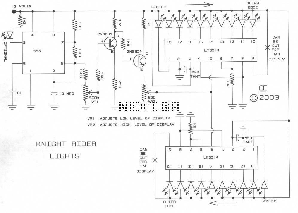
New Knight Rider LED Board
The TL082 (Or a TL072 also is OK) Creates an Adjustable Sawtooth Generator. (It also has a Square wave Output, but it isn`t used here.)
The Left and Right LEDs are connected in series, and if this circuit is used on...
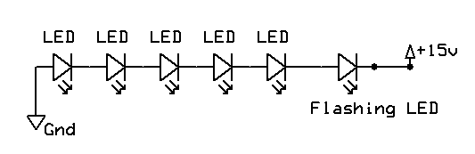
LEDs Revisited
LEDs come in various sizes and shapes, with the most common being round-topped cylinders with diameters of either 3 mm or 5 mm. These sizes are often referred to as T1 (3 mm) and T1 (5 mm). The body of...
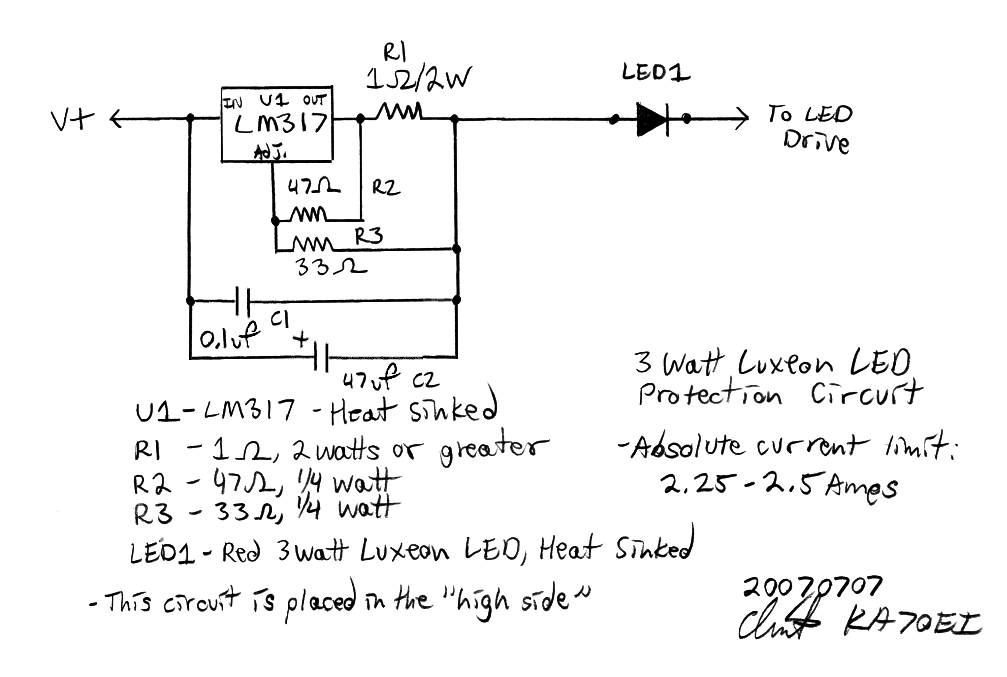
led protection
All optical transmitters will include circuitry designed to limit the current to a safe value that protects the LED during short-term incidents. Red, Red-Orange, and Amber Luxeon I LEDs have a peak current rating of approximately 550 mA. At this...
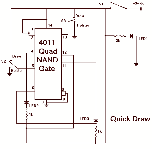
Quick move LED game
The object of Quick Draw is to test your reaction time against your opponent's. A third person acts as a referee and begins the duel by pressing S1, which lights LED1. Upon seeing LED1 go on, you try to outdraw...
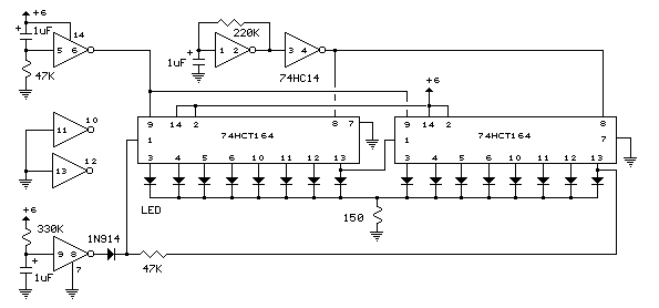
Led circuits
The circuit below illustrates powering one or two LEDs from the 120-volt AC line using a capacitor to drop the voltage and a small resistor to limit the inrush current. Since the capacitor must pass current in both directions, a...
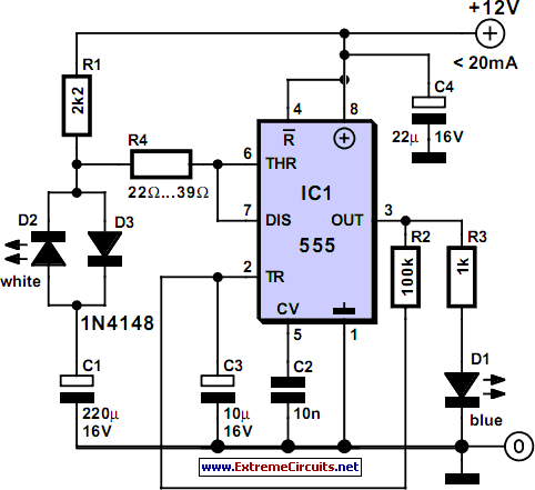
Bluish Flasher
The circuit illustrates how the combination of a blue LED and a white LED can be utilized to create a realistic imitation of a camera flashlight.
The circuit design employs a blue LED and a white LED in conjunction to simulate...
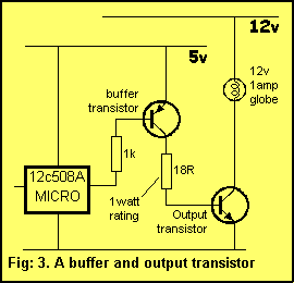
508A microcontroller can deliver a maximum of 25mA
A typical device that requires less than 5v and draws less than 25mA is an LED. A LED must be supplied with an exact voltage for it to operate correctly. Because it requires LESS than 5v, a dropper resistor (current...
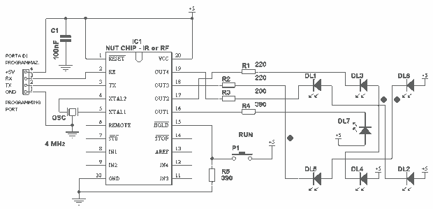
Electronic dice with 7 LED
This project takes advantage from -HOLD input, which is connected to push-button P1. As long as the -HOLD input is low, truth table's timeouts have no effect because this input serves to disable any state change provoked by timers. The...
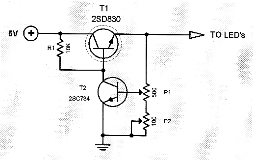
LED dimmer circuit
Typical segment display LEDs consume around 25 mA for each segment and should be limited to this current with resistors. For a six-digit display to be current limited, at least 42 series resistors are needed. The brightness of the LEDs...