


Sensor switch circuit 9 channels
#sensor switch
#74HC147
#high input impedance
#multi-channel
#touch sensor
#logic level
#resistors
#integrated circuits
#ground circuit
#nine channels

Description: This sensor switch circuit features nine channels and consists of three integrated circuits along with several resistors. The 74HC147, which has a high input impedance, enables the use of 4.7 MΩ resistors to establish a logic level "high" for the sensor inputs. When a sensor is activated by touch, it creates a low resistance path to ground, causing IC1 to register a logical level "low."
The sensor switch circuit is designed to manage multiple sensor inputs efficiently, utilizing the 74HC147 priority encoder as its core component. The high input impedance of the 74HC147 allows for minimal loading on the sensors, which is crucial when using high-value resistors like 4.7 MΩ. This configuration ensures that the sensors can operate effectively without significant signal degradation.
In this circuit, each of the nine channels is connected to a separate sensor. When a sensor is activated, it pulls the corresponding input pin of the 74HC147 low, resulting in a logical output that indicates which sensor has been triggered. The output from the 74HC147 can then be fed into additional logic circuits or microcontrollers for further processing, enabling applications such as touch-sensitive interfaces or multi-sensor monitoring systems.
Resistors in the circuit serve dual purposes: they help establish the required input conditions for the 74HC147 and provide necessary pull-up functionality to maintain a stable logic high when the sensors are not activated. The circuit design emphasizes simplicity and reliability, making it suitable for various applications where multiple sensor inputs are needed.
Overall, the described sensor switch circuit is an effective solution for detecting multiple touch inputs with minimal component count while maintaining high performance and reliability.This sensor switch circuit has nine channels and consist of only three integrated circuits and some resistors. Due to high input impedance, 74HC147 allows to use of 4. 7 M resistors to create a logic level "high" to sensor inputs. When one sensor is touched, the resulting low resistance to ground circuit causes IC1 to read a logical level L.
The sensor switch circuit is designed to manage multiple sensor inputs efficiently, utilizing the 74HC147 priority encoder as its core component. The high input impedance of the 74HC147 allows for minimal loading on the sensors, which is crucial when using high-value resistors like 4.7 MΩ. This configuration ensures that the sensors can operate effectively without significant signal degradation.
In this circuit, each of the nine channels is connected to a separate sensor. When a sensor is activated, it pulls the corresponding input pin of the 74HC147 low, resulting in a logical output that indicates which sensor has been triggered. The output from the 74HC147 can then be fed into additional logic circuits or microcontrollers for further processing, enabling applications such as touch-sensitive interfaces or multi-sensor monitoring systems.
Resistors in the circuit serve dual purposes: they help establish the required input conditions for the 74HC147 and provide necessary pull-up functionality to maintain a stable logic high when the sensors are not activated. The circuit design emphasizes simplicity and reliability, making it suitable for various applications where multiple sensor inputs are needed.
Overall, the described sensor switch circuit is an effective solution for detecting multiple touch inputs with minimal component count while maintaining high performance and reliability.This sensor switch circuit has nine channels and consist of only three integrated circuits and some resistors. Due to high input impedance, 74HC147 allows to use of 4. 7 M resistors to create a logic level "high" to sensor inputs. When one sensor is touched, the resulting low resistance to ground circuit causes IC1 to read a logical level L.

electronic touch switch circuit schematic
The schematic illustrates the design of a circuit that measures the resistance of the skin and transforms it into a functional switching signal.
This circuit typically employs a resistive sensor, often referred to as a skin resistance sensor or galvanic skin...
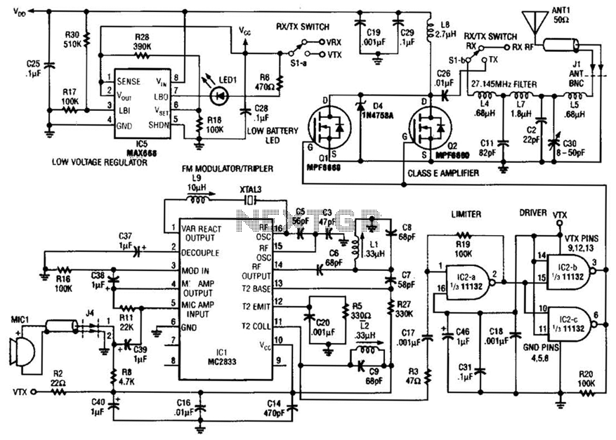
Plate Touch Sensor Circuit
This system operates on the principle that the capacitance loading of an oscillator will lower its frequency. When a foreign body comes into contact with the touch plate, the frequency of U1 is lowered. This removes the oscillator signal from...
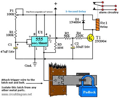
latest touch alarm system circuit
The operating voltage for capacitors C1 and C2 should be raised to 25V if a 12V energy source is used. A general guideline is that the operating voltage of capacitors should be at least double the supplied voltage; for instance,...
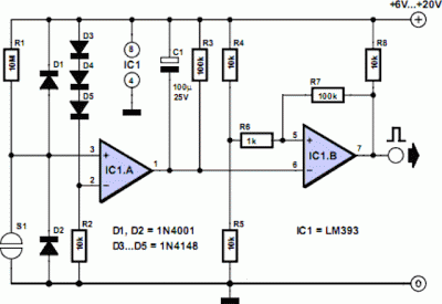
electronic touch switch
The schematic illustrates a circuit designed to sense skin resistance and convert it into a functional switching signal. Touch switch contacts can be constructed from small metal plates, rivets, or nails, positioned closely on a non-conductive surface. The circuit utilizes...
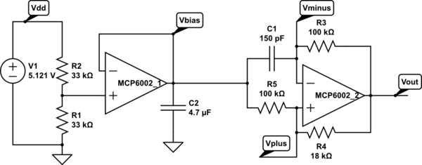
sensors circuit
A touch sensor relaxation oscillator is utilized in the hysteresis lab. In this schematic, the variable capacitor is represented by a person's finger and a touch plate made from aluminum foil and packing tape. Code was developed for the KL25Z...
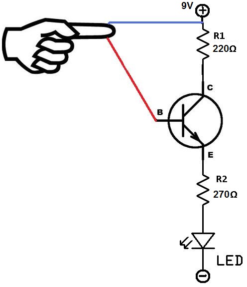
Touch Sensor Circuit
This project utilizes two wires, one red and one blue, which function as touch sensor wires. When a person touches both wires, the circuit closes, allowing current to flow and illuminate the LED. A 9-volt battery or an external power...
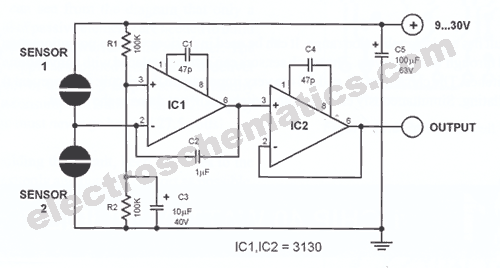
Touch potentiometer circuit
This sensitive touch potentiometer utilizes IC1 (CA3130), an operational amplifier known for its high input impedance. When a finger touches the Se1 sensor, C2...
This circuit design incorporates a touch-sensitive potentiometer that leverages the CA3130 operational amplifier to achieve high sensitivity...
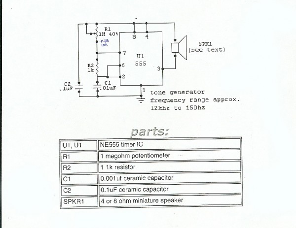
Circuits
To prevent soldering errors, students were instructed to place all their resistors on the board first. Once their placements were verified, they could proceed with soldering. Capacitors were next, followed by LEDs and other components. The middle school class demonstrated...
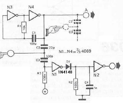
Touch sensor switch using inverters
This touch sensor switch is designed using inverters (N1, N2) and several common electronic components. In the standby state, a signal is produced by oscillator N3/N4 at the inputs of N1. When the touch sensor is activated, the hand capacitance...