


Simple and practical human approach detector circuit diagram
#human approach detector
#operational amplifier
#gate circuit
#oscillator
#copper clad plate
#inductor
#square signal
#1MHz crystal oscillator
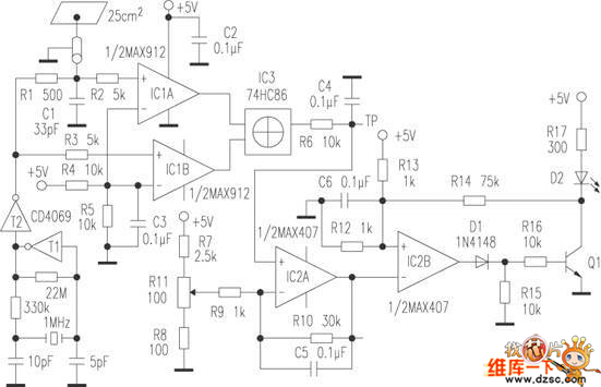
Description: The human approach detector circuit consists of an integrated operational amplifier, a gate circuit, and a resistor-capacitor unit as illustrated in the diagram. The 1 MHz oscillator is composed of a reverser T1, a 1 MHz crystal oscillator, and a resistor-capacitor unit. The signal generated by the oscillator is shaped by T2, which outputs a square wave signal. An inductor is formed using a copper-clad plate measuring 25 cm².
The human body acts as an additional polar plate when in proximity to the copper-clad plate, resulting in an increase in capacitance as the individual approaches. This capacitance varies between 2 to 6 pF. The change in capacitance produces a pulse signal at the output of IC3, with the pulse duty cycle being directly proportional to the incremental capacitance. One output of the square wave from T2 is sent to comparator IC1B via resistor R3 and then to one input of XOR gate IC3 after amplification. The other output is first delayed by R1 and C1, amplified by comparator IC1A, and then sent to the second input of XOR gate IC3. Consequently, the duty cycle of the output square wave from XOR gate IC3 is directly proportional to the delay introduced by R1 in the input circuit. This configuration generates a direct current that correlates with the distance of the human approach, which is subsequently filtered by R6 and C4.
The human approach detector circuit is designed to sense the proximity of a human body through changes in capacitance. The oscillator circuit operates at 1 MHz, providing a stable frequency for the detection mechanism. The integrated operational amplifiers (IC1A and IC1B) play a crucial role in signal conditioning, amplifying the signals derived from the oscillator and the capacitive changes caused by human presence.
The XOR gate (IC3) serves as the final processing stage, where the two inputs—one from the direct oscillator output and the other from the delayed signal—are compared. This comparison results in a pulse signal whose duty cycle varies with the distance of the human approach, effectively translating the capacitive change into a measurable output.
The filtering components (R6 and C4) ensure that the output signal is smoothed, removing high-frequency noise and providing a stable DC output that reflects the detected proximity. This output can be utilized in various applications, such as security systems, automatic lighting controls, or interactive devices that respond to human presence. The design emphasizes efficiency and reliability, making it suitable for a range of electronic applications requiring proximity detection.Human approach detector circuit is composed of integrated operational amplifier, gate circuit and resistor-capacitor unit in the diagram. Among them, 1MHz oscillator consists of reverser T1, 1MHz crystal oscillator and resistor-capacitor unit.
The oscillator signal is shaped by T2 and then T2 outputs square signal. It adopts a piece of 25cm2 copper clad plates to make up inductor. Human body is equal to another polar plate when human nears the copper clad plate. It can generate capacitance enlarge along with human`s approach and the capacity is 2~6pF. This incremental capacitance can make the after IC3 output pulse signal which pulse duty factor is proportional to incremental capacitance. One way of T2 outputted square wave is sent to comparer IC1B by R3, and is add to one input end of XOR gate IC3 after enlarged; another way is first delayed by R1 and C1, than enlarged by comparer IC1A and added to another input end of XOR gate IC3, thereby the duty factor of XOR gate IC3 outputted square signal is in direct proportion to the delay of R1 in the input circuit, then it generates DC current which is in direct proportion to the distance of human approach after filtered by R6 and C4.
The human body acts as an additional polar plate when in proximity to the copper-clad plate, resulting in an increase in capacitance as the individual approaches. This capacitance varies between 2 to 6 pF. The change in capacitance produces a pulse signal at the output of IC3, with the pulse duty cycle being directly proportional to the incremental capacitance. One output of the square wave from T2 is sent to comparator IC1B via resistor R3 and then to one input of XOR gate IC3 after amplification. The other output is first delayed by R1 and C1, amplified by comparator IC1A, and then sent to the second input of XOR gate IC3. Consequently, the duty cycle of the output square wave from XOR gate IC3 is directly proportional to the delay introduced by R1 in the input circuit. This configuration generates a direct current that correlates with the distance of the human approach, which is subsequently filtered by R6 and C4.
The human approach detector circuit is designed to sense the proximity of a human body through changes in capacitance. The oscillator circuit operates at 1 MHz, providing a stable frequency for the detection mechanism. The integrated operational amplifiers (IC1A and IC1B) play a crucial role in signal conditioning, amplifying the signals derived from the oscillator and the capacitive changes caused by human presence.
The XOR gate (IC3) serves as the final processing stage, where the two inputs—one from the direct oscillator output and the other from the delayed signal—are compared. This comparison results in a pulse signal whose duty cycle varies with the distance of the human approach, effectively translating the capacitive change into a measurable output.
The filtering components (R6 and C4) ensure that the output signal is smoothed, removing high-frequency noise and providing a stable DC output that reflects the detected proximity. This output can be utilized in various applications, such as security systems, automatic lighting controls, or interactive devices that respond to human presence. The design emphasizes efficiency and reliability, making it suitable for a range of electronic applications requiring proximity detection.Human approach detector circuit is composed of integrated operational amplifier, gate circuit and resistor-capacitor unit in the diagram. Among them, 1MHz oscillator consists of reverser T1, 1MHz crystal oscillator and resistor-capacitor unit.
The oscillator signal is shaped by T2 and then T2 outputs square signal. It adopts a piece of 25cm2 copper clad plates to make up inductor. Human body is equal to another polar plate when human nears the copper clad plate. It can generate capacitance enlarge along with human`s approach and the capacity is 2~6pF. This incremental capacitance can make the after IC3 output pulse signal which pulse duty factor is proportional to incremental capacitance. One way of T2 outputted square wave is sent to comparer IC1B by R3, and is add to one input end of XOR gate IC3 after enlarged; another way is first delayed by R1 and C1, than enlarged by comparer IC1A and added to another input end of XOR gate IC3, thereby the duty factor of XOR gate IC3 outputted square signal is in direct proportion to the delay of R1 in the input circuit, then it generates DC current which is in direct proportion to the distance of human approach after filtered by R6 and C4.

Stable Start-Stop Oscillator
Oscillators that generate a predetermined number of pulses are often required in applications such as video work. This oscillator starts 13 ms after the control signal goes high and stops immediately when the input signal goes low.
In electronic applications, pulse...
Saw Transmitter Circuit
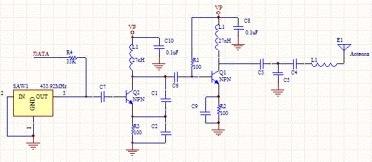
This circuit utilizes a sawtooth oscillator along with an output amplifier that drives a transistor. The components C1, C2, and L1 are essential for the oscillator's operation, forming a tank circuit that must be tuned to the resonant frequency. Generally,...
Field-programmable Operational Transresistance Amplifier using Floating-gate MOSFETs
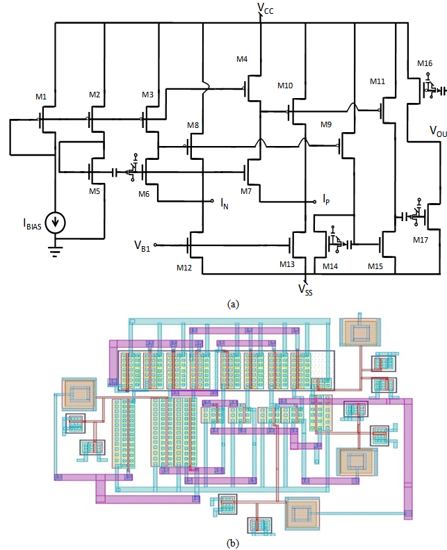
A comprehensive design procedure is proposed for the development of Field-programmable/Reconfigurable Analog Integrated CMOS circuits. Instead of relying on iterative simulation steps to meet design specifications by adjusting the W/L ratios of the FETs, first-order classroom equations are utilized to...
Micro Power AM Broadcast Transmitter
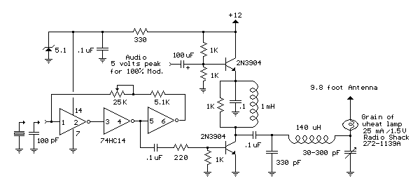
This circuit utilizes a 74HC14 hex Schmitt trigger inverter as a square wave oscillator to drive a small signal transistor configured in a class C amplifier setup. The frequency of the oscillator can be either fixed using a crystal or...
Metal detector 4
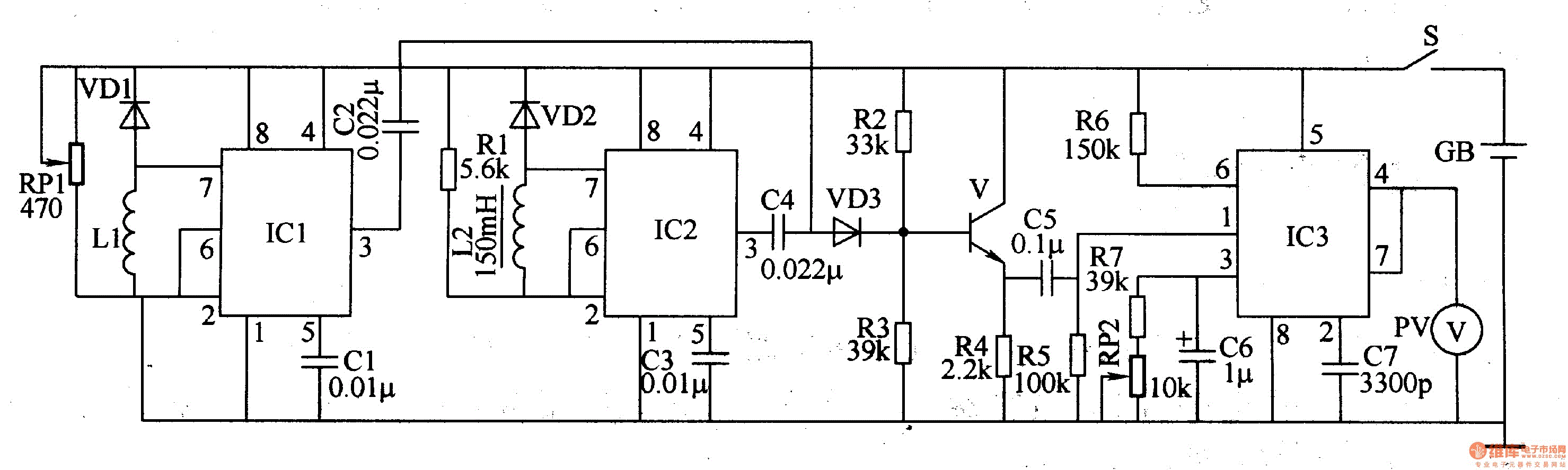
The metal detector circuit comprises a detection oscillator, a reference oscillator, a mixer, and a signal display, as illustrated in Figure 8-70. The detection oscillator circuit is made up of the time base oscillator IC1, inductor L1, potentiometer RP1, diode...
Half-duty-cycle-oscillator
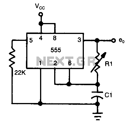
The frequency of oscillation depends on the Rl/Cl time constant, allowing for frequency adjustment by varying Rl. This is a basic circuit.
The described circuit operates based on the relationship between resistance (Rl) and capacitance (Cl), which together form a time...
High drive oscillator-flasher
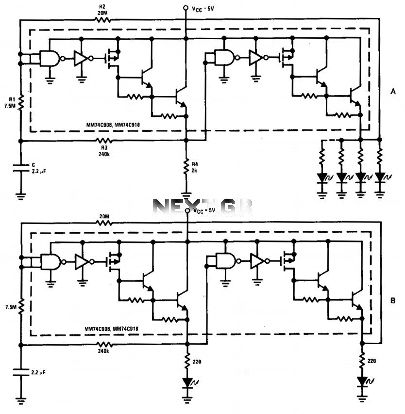
The driver in the package is configured as a Schmitt trigger oscillator (A), utilizing resistors R1 and R2 to create hysteresis. The inverting feedback timing components consist of resistor R3 and capacitor C, while resistor R4 serves as the pull-down...
Inductor saturation tester alternative route to dump the excess energy
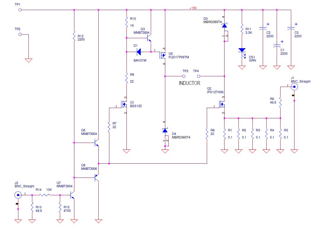
Yes, it does charge the inductor again. Diodes are beneficial as they do not charge the inductor back but dissipate a significant amount of instantaneous power due to the forward voltage drop. One approach would be to monitor the current...
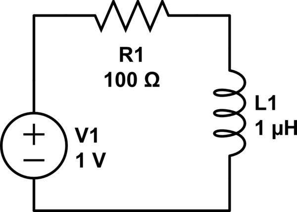
inductor Cutting an RL Circuit
Consider a circuit consisting of a voltage source, a resistor, and an inductor arranged in a closed loop. When the voltage source is activated, the circuit reaches a steady state, during which the inductor stores energy calculated by the formula...