


Simple Light Detector with Sensitivity Control
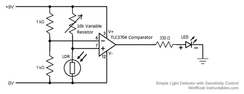
Description: The schematic diagram for the circuit is provided in the accompanying image. As indicated by its name, a comparator is designed to compare two specified voltages. The circuit includes a pair of 1K resistors.
A comparator circuit typically utilizes operational amplifiers (op-amps) configured to compare two input voltage levels. The output of the comparator indicates which of the two input voltages is higher. The circuit consists of two main inputs, referred to as the inverting (-) and non-inverting (+) inputs. The non-inverting input receives one voltage signal, while the inverting input receives the other.
In this specific schematic, the 1K resistors likely serve as part of a voltage divider or feedback network, which can help set reference levels or control the gain of the comparator. The output of the comparator is usually a digital signal that swings between the supply voltage levels, indicating the comparison result. If the voltage at the non-inverting input exceeds that of the inverting input, the output will transition to a high state, typically close to the positive supply voltage. Conversely, if the voltage at the inverting input is higher, the output will drop to a low state, usually near ground.
Additional components may include power supply connections, decoupling capacitors for stability, and possibly indicators such as LEDs to visually represent the output state. The schematic may also specify additional operational parameters such as input voltage ranges, output load capabilities, and response times, which are crucial for ensuring the comparator functions correctly within its intended application.The schematic diagram for the circuit is given in the picture above. Like its name suggests, a comparator compares two given voltages. The pair of 1K..
A comparator circuit typically utilizes operational amplifiers (op-amps) configured to compare two input voltage levels. The output of the comparator indicates which of the two input voltages is higher. The circuit consists of two main inputs, referred to as the inverting (-) and non-inverting (+) inputs. The non-inverting input receives one voltage signal, while the inverting input receives the other.
In this specific schematic, the 1K resistors likely serve as part of a voltage divider or feedback network, which can help set reference levels or control the gain of the comparator. The output of the comparator is usually a digital signal that swings between the supply voltage levels, indicating the comparison result. If the voltage at the non-inverting input exceeds that of the inverting input, the output will transition to a high state, typically close to the positive supply voltage. Conversely, if the voltage at the inverting input is higher, the output will drop to a low state, usually near ground.
Additional components may include power supply connections, decoupling capacitors for stability, and possibly indicators such as LEDs to visually represent the output state. The schematic may also specify additional operational parameters such as input voltage ranges, output load capabilities, and response times, which are crucial for ensuring the comparator functions correctly within its intended application.The schematic diagram for the circuit is given in the picture above. Like its name suggests, a comparator compares two given voltages. The pair of 1K..

Comparator with time out
The MC1422 functions as a comparator with the input at Pin 5. The frequency of the output pulses, dependent on the values of R2 and C1 as indicated, is approximately 2 Hz, with a pulse width of 0 ms at...
Simple Analogue Electronic Key
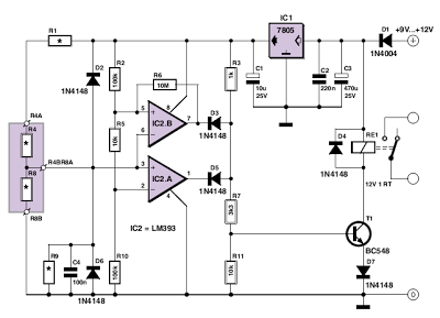
This circuit utilizes two comparators configured as a window comparator. Resistors R2, R5, and R10 establish a voltage window within which the voltage at the junction of D2 and D6 must reside for the outputs of IC2.A and IC2.B to...
Light Detector
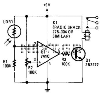
The circuit's threshold is determined by resistor R2. When the intensity of light on the LDR decreases, the resistance of the LDR increases, resulting in a lower voltage at the inverting input of the 741 operational amplifier. The reference voltage...
Tunable single comparator oscillator
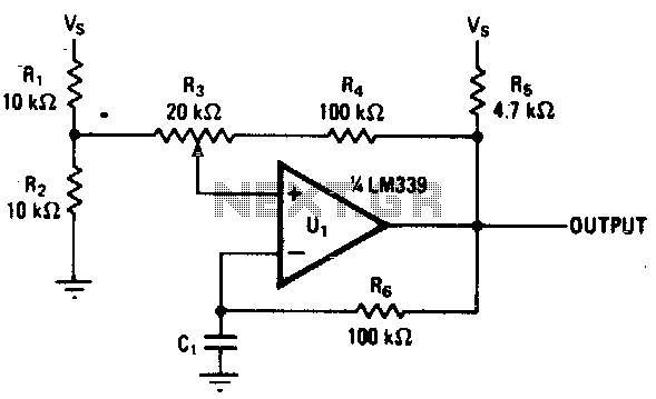
Varying the amount of hysteresis in this comparator circuit allows for smooth adjustment of output frequencies within the range of 740 Hz to 2 kHz. The hysteresis level, in combination with the time constant formed by resistor R6 and capacitor...
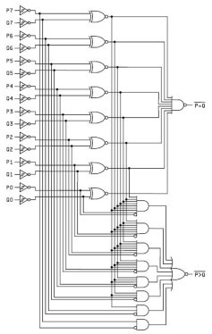
IC Magnitude Comparators
This Magnitude Comparator can be used to perform comparisons of two 8-bit binary or BCD words. The output provides both a P equals Q function and a P greater than Q function. A Magnitude Comparator is typically classified as standard...
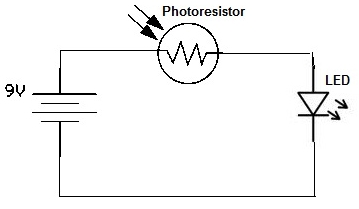
Simple Photoresistor Circuit
A simple photoresistor circuit will be constructed to demonstrate the operation of a photoresistor, which activates the circuit in the presence of light and deactivates it in darkness. This circuit connects a photoresistor to an LED. When the photoresistor is...
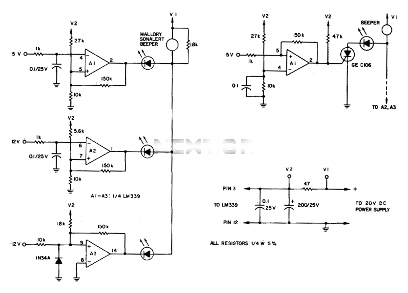
Comparator for over-voltages
To maintain an alarm condition when an overvoltage transient disappears, an SCR should be added to the comparator circuits. For SCR operation, the voltages to the comparator inputs are inverted. The triple-voltage monitoring circuit detects transient power-supply over-voltages. If excessive...
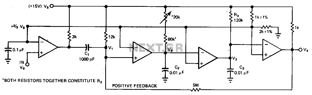
Frequency-detecting-comparator
A quad comparator serves as the foundation for a frequency detector that is both faster and more cost-effective than more complex alternatives utilizing frequency-to-voltage converter chips. Positive feedback through a 5 MΩ resistor enables the circuit to detect changes as...

High input comparator
The circuit utilizes both halves of the CA3290 BiMOS dual voltage comparator. The LED will be activated whenever the input signal is above the lower limit (VL) but below the upper limit (Vy).
The circuit design employs the CA3290 BiMOS dual...