


Temperature to Digital ConverterCircuit using LM35
#LM35
#temperature sensor
#digital converter
#bypass capacitor
#RC damper
#analog sensor
#voltage output
#precision sensor
#temperature measurement
#sensor interface
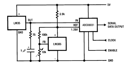
Description: The circuit illustrates a Temperature to Digital Converter diagram utilizing the LM35 sensor, which includes a beneficial bypass capacitor connected from VIN to ground and a series RC damper.
The described circuit employs the LM35 temperature sensor, a precision integrated circuit that outputs an analog voltage proportional to the temperature in degrees Celsius. The LM35 is known for its ease of use, as it does not require any external calibration and offers a linear output of 10 mV per degree Celsius.
In this configuration, the bypass capacitor serves a critical role in stabilizing the power supply voltage at the VIN pin of the LM35. By connecting the capacitor from VIN to ground, it filters out any high-frequency noise that may be present in the power supply line, thereby ensuring stable operation of the sensor. Proper bypassing is essential for accurate temperature readings, as fluctuations in supply voltage can lead to erroneous output signals.
The series RC damper included in the circuit is designed to mitigate any potential overshoot or ringing in the output signal. This is particularly important when interfacing the LM35 with an analog-to-digital converter (ADC), as rapid changes in temperature can produce transient spikes in the output voltage. The RC damper works by introducing a time constant that smooths out the response of the circuit, allowing for more stable and reliable readings.
Overall, the combination of the LM35 sensor, the bypass capacitor, and the series RC damper creates a robust temperature measurement system that can be effectively integrated into various electronic applications, such as environmental monitoring, HVAC systems, and temperature control mechanisms.Above circuit shows Temperature to Digital Converter diagram using this LM35 sensor with a useful bypass capacitor from VIN to ground and a series RC damper
The described circuit employs the LM35 temperature sensor, a precision integrated circuit that outputs an analog voltage proportional to the temperature in degrees Celsius. The LM35 is known for its ease of use, as it does not require any external calibration and offers a linear output of 10 mV per degree Celsius.
In this configuration, the bypass capacitor serves a critical role in stabilizing the power supply voltage at the VIN pin of the LM35. By connecting the capacitor from VIN to ground, it filters out any high-frequency noise that may be present in the power supply line, thereby ensuring stable operation of the sensor. Proper bypassing is essential for accurate temperature readings, as fluctuations in supply voltage can lead to erroneous output signals.
The series RC damper included in the circuit is designed to mitigate any potential overshoot or ringing in the output signal. This is particularly important when interfacing the LM35 with an analog-to-digital converter (ADC), as rapid changes in temperature can produce transient spikes in the output voltage. The RC damper works by introducing a time constant that smooths out the response of the circuit, allowing for more stable and reliable readings.
Overall, the combination of the LM35 sensor, the bypass capacitor, and the series RC damper creates a robust temperature measurement system that can be effectively integrated into various electronic applications, such as environmental monitoring, HVAC systems, and temperature control mechanisms.Above circuit shows Temperature to Digital Converter diagram using this LM35 sensor with a useful bypass capacitor from VIN to ground and a series RC damper
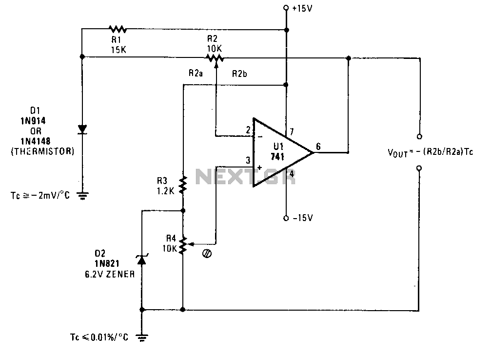
Thermometer-adapter
A simple operational amplifier and silicon diode form the core of a temperature-to-voltage converter, which allows the use of a standard voltmeter—either analog or digital—to measure temperature. User adjustments enable readings of either 10 mV or 100 mV to correspond...
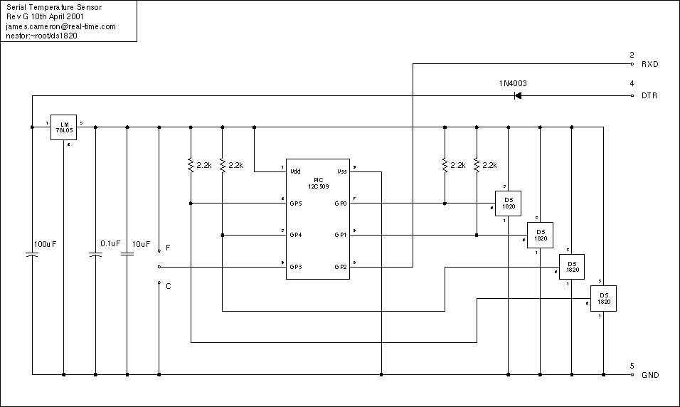
Temperature Sensor Project
Just a handful of components builds an 8-pin microcontroller based circuit for temperature logging via a serial port; small, fast, and acceptably accurate. More: provides real-time data to your computer via serial port, interfaces up to four DS1820 temperature sensors,...
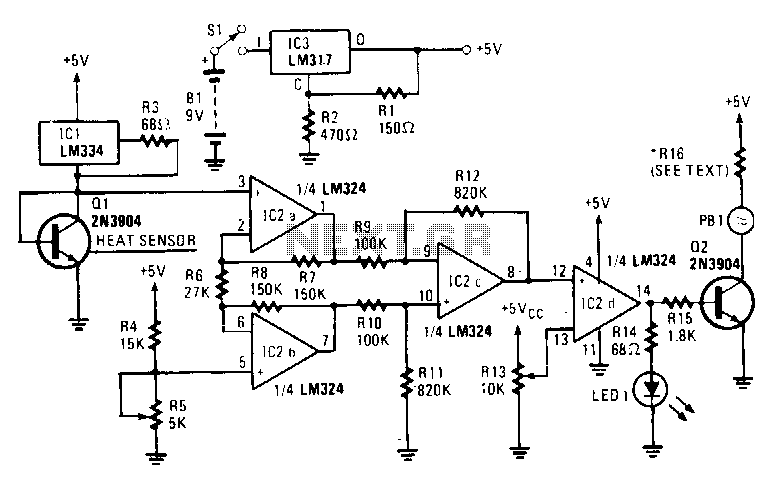
Electronic-heat-sniffer
The sensing element Q1 is a 2N3904 general-purpose NPN transistor, although any general-purpose NPN unit in a TO-92 style case will suffice. IC1, an LM334, provides Q1 with a constant current that remains stable regardless of temperature variations. An LM324...
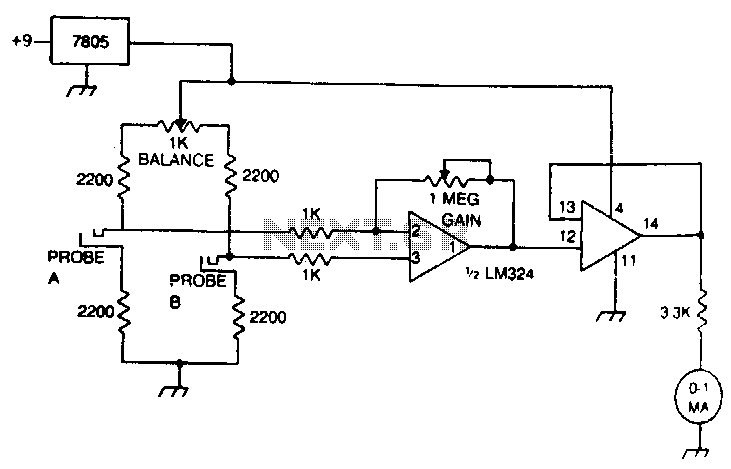
Temperature-reporting-digital-thermometer
The ROMs or PROMs must contain the correct code to convert data from the NE5037, which serves as the address for the ROMs or PROMs, into the appropriate segment driver codes. The displayed temperature can easily be converted to degrees...
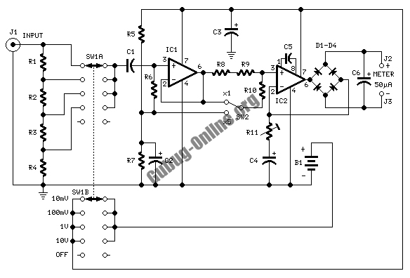
Temperature Relay Circuit
This is a circuit design for a temperature relay that can be used to signal a fire or monitor temperature set points. The adjustment of P1 is necessary to ensure that the base voltage of T1 is 0.5V lower than...
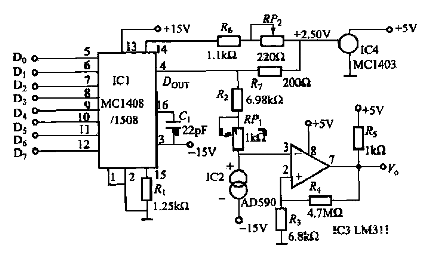
8 NC temperature adjustment
An 8 NC temperature adjusting circuit is presented, primarily composed of a D/A converter, a reference power supply, amplification components, temperature sensors, and other necessary elements. This circuit regulates the temperature within a range of 0-51°C and is suitable for...
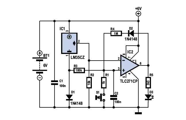
Audio Schematic Frost Detector Temperature Sensor
To determine whether it is freezing, one needs to measure the temperature accurately. This requires a reliable temperature sensor. The LM35CZ sensor, which operates within a range of -40 to 110 °C, is suitable for this purpose. It is relatively...
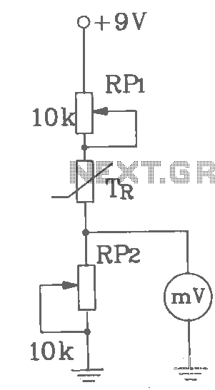
T-121 Temperature sensor circuit diagram (electronic thermometer)
T-121 temperature sensor electronic thermometer circuit diagram shown below
The T-121 temperature sensor circuit is designed to measure and display temperature readings accurately. The circuit typically consists of a temperature sensor, such as the T-121, which converts temperature variations into an...
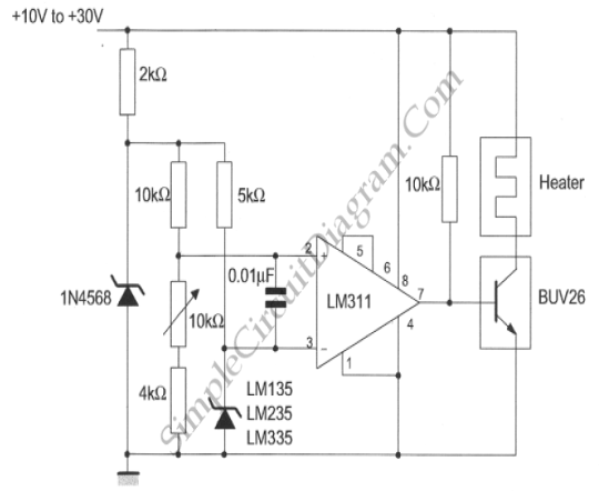
Simple Temperature Controller
This temperature controller utilizes an LM135/235/335 temperature sensor and is designed to maintain a small environment at a warm or hot temperature. A schematic diagram is provided.
The temperature controller circuit is centered around the LM135/235/335 series of temperature sensors, which...