


The proximity switch circuit with integrated magnetic field sensor HMC1001
#HMC1001
#operational amplifier
#comparator
#magnetic field sensor
#proximity switch
#LED
#MR bridge
#voltage output
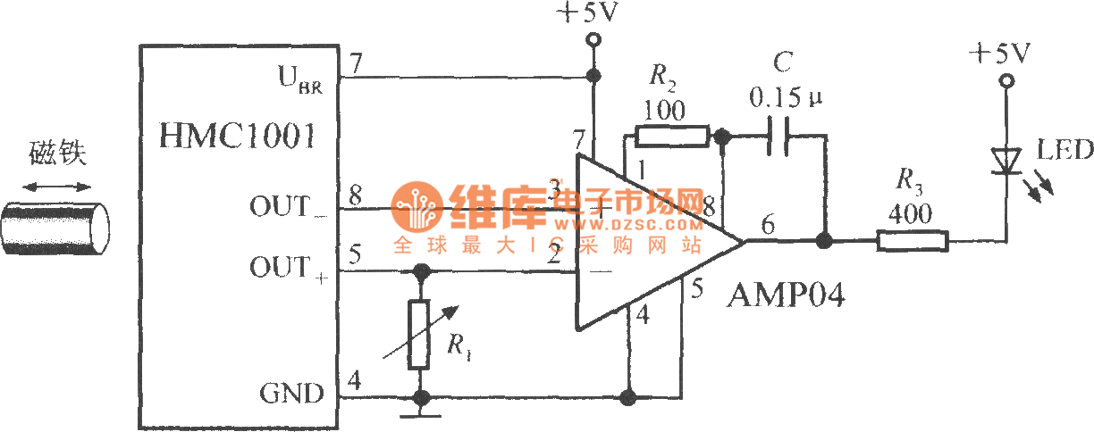
Description: The proximity switch circuit consists of the HMC1001 sensor, operational amplifier (AMP04), and a light-emitting diode (LED). The operational amplifier functions as a comparator. When a magnet, measuring between 6mm and 12mm, is moved to a predetermined position near the HMC1001, the output voltage from the MR bridge reaches 30mV, causing the comparator to switch its output state.
The proximity switch circuit utilizes the HMC1001, a highly sensitive magnetic sensor, which detects the presence of a magnetic field. The operational amplifier (AMP04) is configured in a comparator mode to compare the output voltage from the HMC1001 with a reference voltage.
In this configuration, when the magnet is positioned within the specified range (6mm to 12mm) of the HMC1001, the MR bridge generates an output voltage of 30mV. This voltage is sufficient to exceed the threshold set by the operational amplifier's reference input, resulting in a change in the output state of the comparator. The output of the operational amplifier can then drive an LED, indicating the detection of the magnetic field.
The circuit may include additional components such as resistors to set the reference voltage and capacitors for stability and noise filtering. The LED serves as a visual indicator, illuminating when the magnetic field is detected, providing a clear and immediate response to the presence of the magnet. This circuit is applicable in various automation and sensing applications, where proximity detection is essential for system operation.As shown in figure, the proximity switch circuit is composed of HMC1001, operational amplifier (AMP04) and light emitting diode (LED). The operational amplifier is used as a comparator. When you move magnet with length being 6mm~12mm to HMC1001 in a predetermined position, the output voltage of MR bridge will reach 30mV, then the comparator flips, and output..
The proximity switch circuit utilizes the HMC1001, a highly sensitive magnetic sensor, which detects the presence of a magnetic field. The operational amplifier (AMP04) is configured in a comparator mode to compare the output voltage from the HMC1001 with a reference voltage.
In this configuration, when the magnet is positioned within the specified range (6mm to 12mm) of the HMC1001, the MR bridge generates an output voltage of 30mV. This voltage is sufficient to exceed the threshold set by the operational amplifier's reference input, resulting in a change in the output state of the comparator. The output of the operational amplifier can then drive an LED, indicating the detection of the magnetic field.
The circuit may include additional components such as resistors to set the reference voltage and capacitors for stability and noise filtering. The LED serves as a visual indicator, illuminating when the magnetic field is detected, providing a clear and immediate response to the presence of the magnet. This circuit is applicable in various automation and sensing applications, where proximity detection is essential for system operation.As shown in figure, the proximity switch circuit is composed of HMC1001, operational amplifier (AMP04) and light emitting diode (LED). The operational amplifier is used as a comparator. When you move magnet with length being 6mm~12mm to HMC1001 in a predetermined position, the output voltage of MR bridge will reach 30mV, then the comparator flips, and output..

Light Chaser Ii
Up to six lights can be sequentially flashed using this circuit. LED1 through LED6 can be replaced by optocouplers (MOC3010, etc.) to control 120-Vac loads via triacs. Ul generates pulses that clock the shift register mode of the six D...
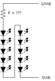
Circuit Diagram for a 12V LED Lamp
The color of the LED makes a significant difference. The type and size of the LED, such as 3mm or 5mm, and the power source are crucial factors to consider. More information is required for accurate calculations. A basic electrical...
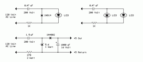
AC Line powered LEDs
The circuit below demonstrates how to power one or two LEDs from a 120-volt AC line. It utilizes a capacitor to reduce the voltage and a small resistor to limit the inrush current. As the capacitor needs to allow current...
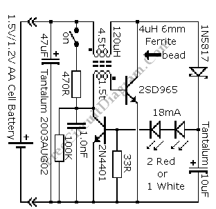
Powering LED from Single AA Cell
The advantage of LED technology is its longer lifespan compared to incandescent lamps, along with higher efficiency in the latest LED advancements. Additionally, LEDs are very compact; however, there are some limitations.
LEDs, or Light Emitting Diodes, are semiconductor devices that...
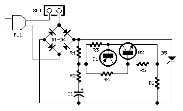
220V LED Flasher circuit diagram
This is a 220V LED flasher circuit designed as a reliable alternative to thermally activated switches used for flashing Christmas tree lamps. It is a cost-effective and easy-to-assemble circuit. The components include R1 (100K), R2 (1K), R5 (1K), R3 (470R),...
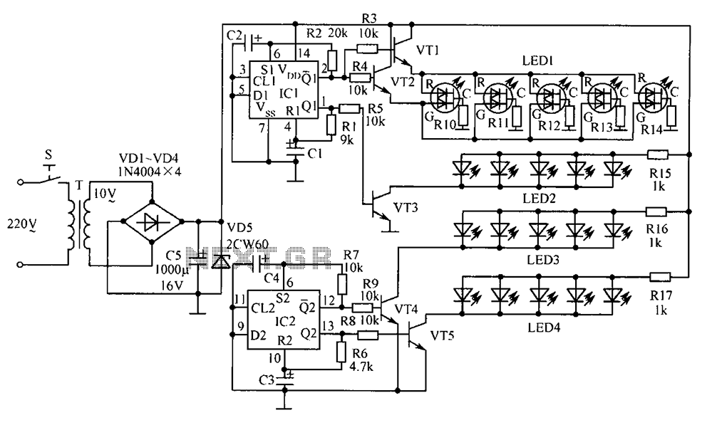
Bonsai electronic circuit
The electronic components designed by conventional electronic bonsai create a sparkling and brilliant atmosphere in the living room, enhancing the joys and pleasures of life. The selection of components includes IC1 to IC4, which consist of two pairs of D...
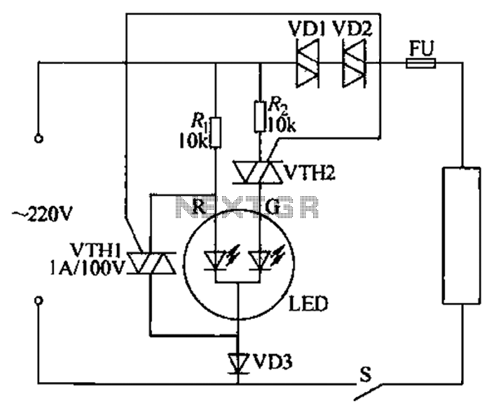
Run through the display circuit equipment Chengdu
Color light-emitting diodes with different colors can indicate the operational status of electrical equipment, as illustrated in the accompanying figure. The red light-emitting diode (LED) R emits red light when energized, indicating that the 220V power supply is functioning normally....
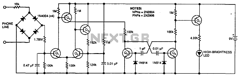
Phone Message Flasher
This circuit flashes an LED to indicate that a phone rang during the user's absence. A differential amplifier with hysteresis (Q1, Q2, and Q3) detects high line voltage (ringing), which activates Q4, a multivibrator composed of Q5 and Q6, and...

10 Step LED Circuit
Each time switch S1 is closed the count on the CD4017 advances by 1 step and the corresponding LED turns on. When the maximum count plus 1 is reached for each circuit the cycle is restarted and repeats.
The circuit utilizes...