


The sound of a photoelectric conversion circuit
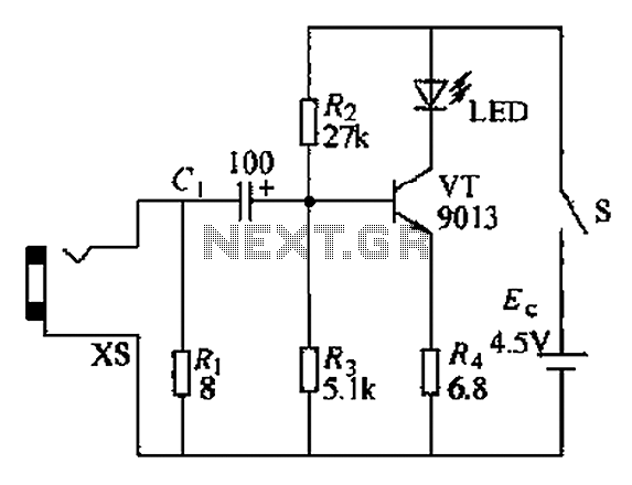
Description: The circuit operates as a light-to-sound conversion system, featuring a light electric sound conversion circuit with two simple fiber optic connectors for experimental purposes. The electrical diagram illustrates the conversion circuit, where audio signals from a radio, music player, or other audio sources are output through a headphone jack. These signals are amplified by a transistor (VT) to drive LED lights, which emit signals modulated by the audio input, completing the electro-optical conversion. The resistor (Ri) serves to match the input impedance of the circuit with the output impedance of devices like radios and Walkmans. The LED light signals, after being transmitted through optical fibers, are received by a photodiode (Ran, VLS), which converts the optical signals back into weak electrical signals. This weak signal is then amplified by a pre-amplifier circuit using a transistor (VT) and other components, before being sent to an LM386 integrated circuit power amplifier. The amplified output drives a speaker (BL), restoring sound and completing the light-to-sound conversion process. The circuit also includes a potentiometer (RP) for volume adjustment.
The circuit design comprises several key components that work together to facilitate the conversion process. The audio input from a source, such as a radio or music player, is fed into the circuit through a dedicated input socket. The initial stage involves the transistor (VT), which acts as an amplifier to boost the audio signal sufficiently to drive the LED. The LED is crucial in this setup, as it converts the electrical audio signal into light, which is then transmitted via the fiber optic cables.
The role of the resistor (Ri) is essential for ensuring that the circuit maintains proper impedance matching. This matching is critical for maximizing power transfer and minimizing signal loss, which is particularly important in audio applications where fidelity is paramount.
Once the light signal travels through the fiber optic connectors, it reaches the photodiode (Ran, VLS). The photodiode functions as a light sensor, converting the incoming light back into an electrical signal. This signal is generally weak and requires further amplification. The pre-amplifier stage, which includes another transistor (VT), boosts the signal strength before it is sent to the LM386 power amplifier.
The LM386 is a low-voltage audio power amplifier that is well-suited for driving small speakers. It is designed to deliver sufficient power to reproduce sound effectively without requiring excessive voltage levels. The output from the LM386 is connected to the speaker (BL), which converts the amplified electrical signal back into audible sound waves.
To enable user control over the output volume, the circuit incorporates a potentiometer (RP). This adjustable resistor allows the user to set the desired sound level, providing flexibility and enhancing the usability of the system.
Overall, this circuit exemplifies a straightforward yet effective approach to converting audio signals into light and back into sound, utilizing basic electronic components to achieve the desired functionality in an experimental setup. Circuit works as follows: The electrical circuit is a light, a light electric sound conversion circuit with two simple fiber optic connector for experimental play is shown. f W hat the electrical diagram showing a conversion circuit. Audio radio, music and other audio Xin headphone jack output from the input socket xs, after VT amplified by the drive LED light signals emitted by audio signals modulated complete electro-optical conversion. Circuit Ri is the role of the circuit input impedance of the radio, Walkman and other audio output impedance matching.
Figure showing b} sound power conversion circuit. LED light signal emitted after the optical fiber transmission received by the photodiode f Ran, VLS converting the received optical signal into an electrical signal weak. This pre-amplifier via the transistor VT and other electrical components of the composition of an enlarged and then sent people LM386 IC power amplifier, speaker BL push restore the sound to achieve a light electric sound conversion.
Circuit RP is the volume adjustment potentiometer.
The circuit design comprises several key components that work together to facilitate the conversion process. The audio input from a source, such as a radio or music player, is fed into the circuit through a dedicated input socket. The initial stage involves the transistor (VT), which acts as an amplifier to boost the audio signal sufficiently to drive the LED. The LED is crucial in this setup, as it converts the electrical audio signal into light, which is then transmitted via the fiber optic cables.
The role of the resistor (Ri) is essential for ensuring that the circuit maintains proper impedance matching. This matching is critical for maximizing power transfer and minimizing signal loss, which is particularly important in audio applications where fidelity is paramount.
Once the light signal travels through the fiber optic connectors, it reaches the photodiode (Ran, VLS). The photodiode functions as a light sensor, converting the incoming light back into an electrical signal. This signal is generally weak and requires further amplification. The pre-amplifier stage, which includes another transistor (VT), boosts the signal strength before it is sent to the LM386 power amplifier.
The LM386 is a low-voltage audio power amplifier that is well-suited for driving small speakers. It is designed to deliver sufficient power to reproduce sound effectively without requiring excessive voltage levels. The output from the LM386 is connected to the speaker (BL), which converts the amplified electrical signal back into audible sound waves.
To enable user control over the output volume, the circuit incorporates a potentiometer (RP). This adjustable resistor allows the user to set the desired sound level, providing flexibility and enhancing the usability of the system.
Overall, this circuit exemplifies a straightforward yet effective approach to converting audio signals into light and back into sound, utilizing basic electronic components to achieve the desired functionality in an experimental setup. Circuit works as follows: The electrical circuit is a light, a light electric sound conversion circuit with two simple fiber optic connector for experimental play is shown. f W hat the electrical diagram showing a conversion circuit. Audio radio, music and other audio Xin headphone jack output from the input socket xs, after VT amplified by the drive LED light signals emitted by audio signals modulated complete electro-optical conversion. Circuit Ri is the role of the circuit input impedance of the radio, Walkman and other audio output impedance matching.
Figure showing b} sound power conversion circuit. LED light signal emitted after the optical fiber transmission received by the photodiode f Ran, VLS converting the received optical signal into an electrical signal weak. This pre-amplifier via the transistor VT and other electrical components of the composition of an enlarged and then sent people LM386 IC power amplifier, speaker BL push restore the sound to achieve a light electric sound conversion.
Circuit RP is the volume adjustment potentiometer.
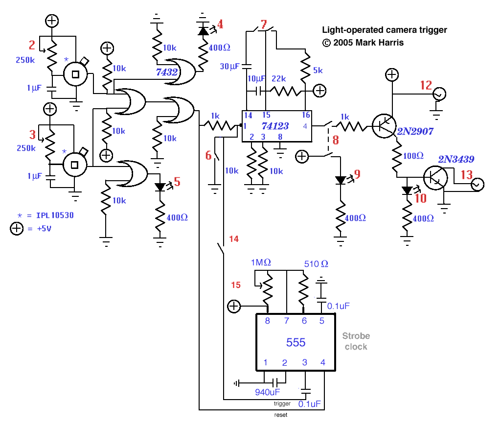
home-made light-operated camera trigger
This device is designed to capture images of moving objects by activating a camera or flashgun when one or two light beams are interrupted. Originally intended for photographing insects in flight, it can also be utilized for projectiles and other...
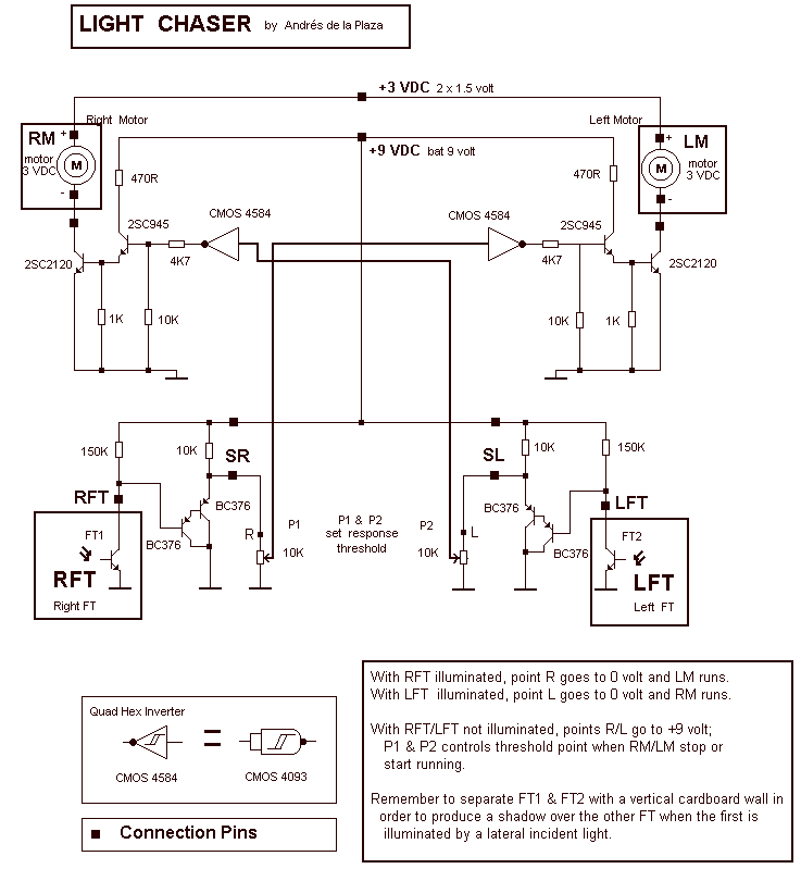
Sun Light Chaser
With RFT illuminated, point R goes to 0 volt and LM runs. With LFT illuminated, point R goes to 0 volt and RM runs. With RFT and/or LFT not illuminated, points R/L go to +9 volt; P1 and P2 controls...
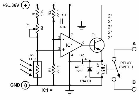
light activated switch
The brightness of the surrounding light controls the function of this circuit. The light sensor used in this circuit is a light-dependent resistor (LDR). This LDR is connected to the non-inverting input of the 741 op-amp IC. Once the intensity...
Low-light-level-drop-detector
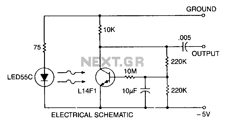
This self-biasing configuration is useful whenever small changes in light level must be detected, such as when monitoring very low flow rates by counting drops of fluid. In this bias method, the photodarlington is bias stabilized by feedback from the...
Light-Controlled Pond Pump
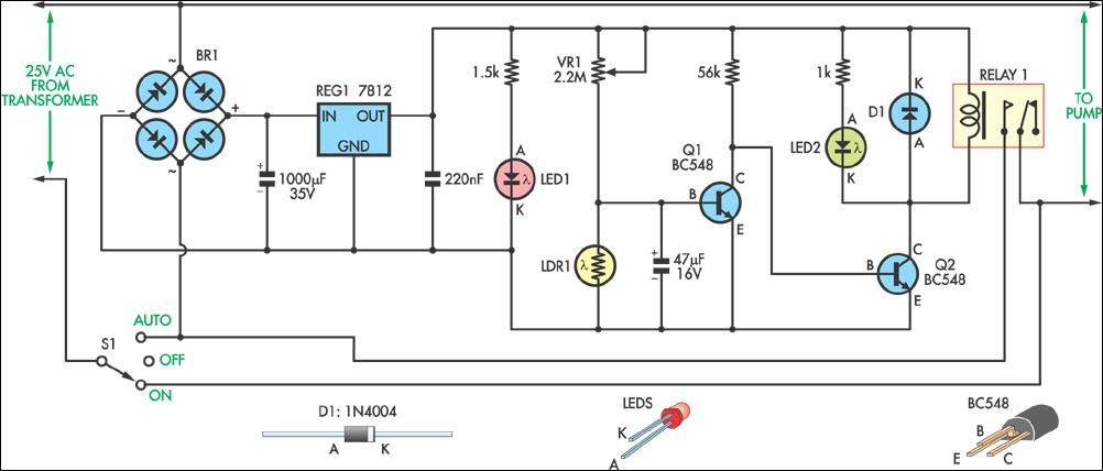
This circuit was designed to automatically control a garden pond pump, turning it on at dawn and off at dusk. This automation eliminates the need for manual operation, particularly beneficial during holidays when the owners are away. The controller derives...
Light-Controlled Pond Pump
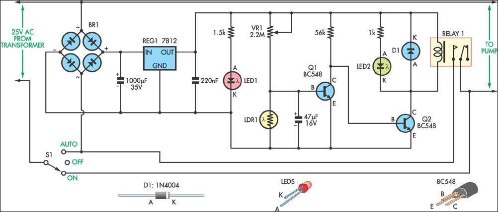
This circuit was designed to control a pump in a garden pond, enabling it to automatically activate at dawn and deactivate at dusk.
The circuit utilizes a light-dependent resistor (LDR) to detect ambient light levels, which serves as the primary sensor...
Photoelectric switch
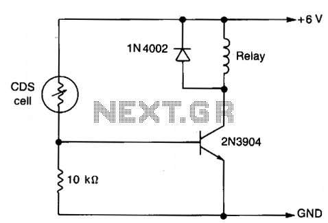
The resistance of the CDS cell decreases when exposed to light, activating the 2N3904 relay driver.
The circuit utilizes a Cadmium Sulfide (CDS) photoresistor, which is a light-dependent resistor that changes its resistance based on the intensity of light it...
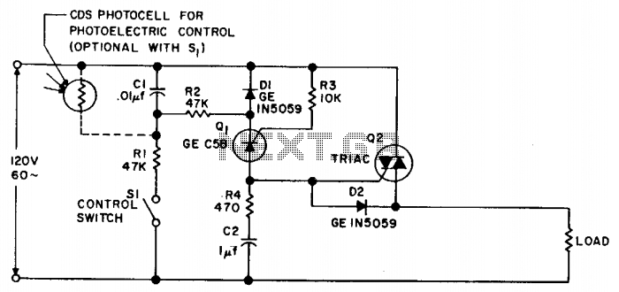
Photoelectric switch
Synchronous switching activates only when the AC supply voltage crosses zero and deactivates only when the current reaches zero. This circuit responds to either a mechanical switch or a variable resistance, such as a cadmium-sulfide photocell. It minimizes disturbances to...
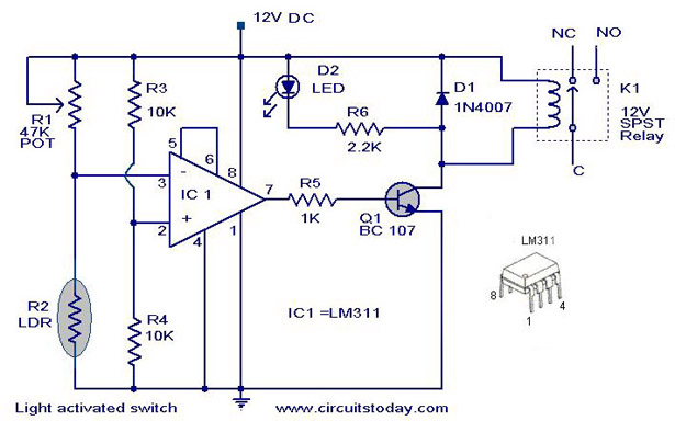
Light Activated SwitchCircuit Based On The LM311 IC
The following circuit illustrates a Light Activated Switch Circuit Diagram. This circuit is based on the LM311 integrated circuit, which functions as a voltage comparator.
The Light Activated Switch Circuit utilizes the LM311 voltage comparator to control the switching of a...