


The timing of the flip-flop circuit composed of a photodiode etc.
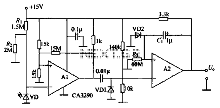
Description: The circuit includes comparators A1 and A2, which function as a single-trigger timing device. When the light is interrupted, the current through photodiode VD changes. The output of A1 triggers A2, causing A2's output to go low and remain at that low level for 60 seconds (as determined by the resistor and capacitor values). Variations in static resistance can alter the sensitivity of VD to light, but the ratio for protection remains unchanged, allowing for some anti-bias voltage. Component parameters are selected as depicted in Figure 3-20, which does not impose any special requirements. The timing circuit is activated by a photodiode or similar device.
The circuit operates using a pair of comparators, A1 and A2, configured in a timing application. Comparator A1 monitors the current flowing through photodiode VD, which is sensitive to light. When the light source is interrupted, the current through the photodiode decreases, triggering the output of comparator A1. This output serves as a control signal for comparator A2, which subsequently switches its output state to low.
The low output from A2 is designed to persist for a predetermined duration of 60 seconds, which is established by the time constant of the associated resistor-capacitor (RC) network. This timing function is critical in applications where a delay is required before returning to a high state, allowing for the detection of transient interruptions in the light source.
Adjustments to the static resistance within the circuit can influence the sensitivity of the photodiode to varying light levels. However, it is essential to maintain the protection ratio to ensure the circuit's stability and reliability. The design incorporates provisions for anti-bias voltage, which helps to mitigate fluctuations that could lead to erroneous triggering of the comparators.
The components used in this circuit, as illustrated in Figure 3-20, are standard and do not have any special requirements, allowing for ease of implementation. The timing circuit's activation through a photodiode or similar device provides flexibility in various applications, making it suitable for environments where light interruption needs to be monitored and responded to appropriately. This configuration is beneficial in security systems, automated lighting controls, and other similar applications where light detection is crucial. Circuit, the comparator Al, A2 is a single trigger timing device. When the light is interrupted, photodiode VD of current changes. Al output trigger A2, A2 output goes low and 60s (the Island and cl Huan set) remains within the low level. Horse and surprised static resistance change can change the VD sensitivity to light tincture but its ratio to protect unchanged so as V) provides some anti- bias voltage. (2) Component parameters: Component selected in Figure 3-20 shows the new, no special requirements. (3) As shown in the timing circuit is triggered by a photodiode or the like of
The circuit operates using a pair of comparators, A1 and A2, configured in a timing application. Comparator A1 monitors the current flowing through photodiode VD, which is sensitive to light. When the light source is interrupted, the current through the photodiode decreases, triggering the output of comparator A1. This output serves as a control signal for comparator A2, which subsequently switches its output state to low.
The low output from A2 is designed to persist for a predetermined duration of 60 seconds, which is established by the time constant of the associated resistor-capacitor (RC) network. This timing function is critical in applications where a delay is required before returning to a high state, allowing for the detection of transient interruptions in the light source.
Adjustments to the static resistance within the circuit can influence the sensitivity of the photodiode to varying light levels. However, it is essential to maintain the protection ratio to ensure the circuit's stability and reliability. The design incorporates provisions for anti-bias voltage, which helps to mitigate fluctuations that could lead to erroneous triggering of the comparators.
The components used in this circuit, as illustrated in Figure 3-20, are standard and do not have any special requirements, allowing for ease of implementation. The timing circuit's activation through a photodiode or similar device provides flexibility in various applications, making it suitable for environments where light interruption needs to be monitored and responded to appropriately. This configuration is beneficial in security systems, automated lighting controls, and other similar applications where light detection is crucial. Circuit, the comparator Al, A2 is a single trigger timing device. When the light is interrupted, photodiode VD of current changes. Al output trigger A2, A2 output goes low and 60s (the Island and cl Huan set) remains within the low level. Horse and surprised static resistance change can change the VD sensitivity to light tincture but its ratio to protect unchanged so as V) provides some anti- bias voltage. (2) Component parameters: Component selected in Figure 3-20 shows the new, no special requirements. (3) As shown in the timing circuit is triggered by a photodiode or the like of
PHOTODIODE CURRENT TO VOLTAGE CONVERTER
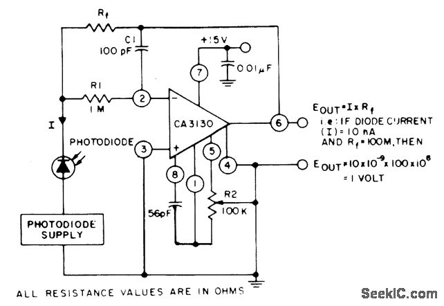
The circuit employs three CA3130 BiMOS operational amplifiers in an application that is sensitive to sub-picoampere input currents. It generates a ground-referenced output voltage that is proportional to the input current flowing through the photodiode.
The described circuit utilizes three CA3130...
Photodiode-source-follower
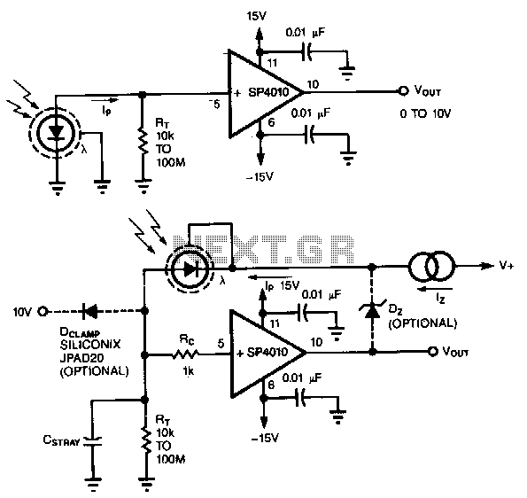
A common method of transforming the output current of a photodiode into a voltage signal involves paralleling the photodiode with a high-value load resistor, which results in a nonlinear response. Additionally, the combination of the load's transresistance, Rr, and the...
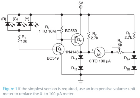
Photo Meter Assesses Ambient Light Schematic
Most PN-junction diodes can be utilized as photodiodes. Although they are not specifically optimized for this purpose, they are functional. When reverse biased, a diode generates a small photovoltaic output that increases with light intensity. Light Emitting Diodes (LEDs) are...
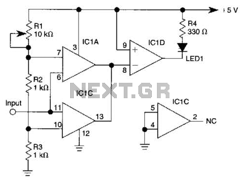
Window Comparator Circuit
IC1-c functions as a non-inverting comparator, while IC1-a operates as an inverting comparator. Potentiometer R1 and fixed resistors R2 and R3 create a voltage divider chain that provides slightly different voltages to the two comparators. These voltages establish the upper...
%2Busing%2Bop%2Bamp%2B741%2Bic%2B.png "Zero Crossing Detector ZCD Comparator circuit using 741 op amp circuit")
Zero Crossing Detector (ZCD): Comparator circuit using 741 op amp
A zero crossing detector (ZCD) is a voltage comparator that switches its output between +Vsat and -Vsat (where Vsat is the saturation voltage, approximately 14V) when the input crosses the zero reference voltage. Comparators are fundamental operational amplifier circuits that...

Comparator with time out
The MC1422 functions as a comparator with the input at Pin 5. The frequency of the output pulses, dependent on the values of R2 and C1 as indicated, is approximately 2 Hz, with a pulse width of 0 ms at...

High input comparator
The circuit utilizes both halves of the CA3290 BiMOS dual voltage comparator. The LED will be activated whenever the input signal is above the lower limit (VL) but below the upper limit (Vy).
The circuit design employs the CA3290 BiMOS dual...
transceiver-circuits
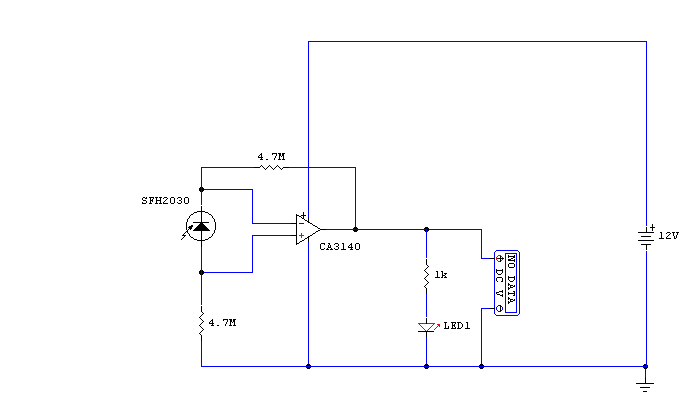
While developing an infrared (IR) extender circuit, a method was needed to measure the relative intensities of different infrared light sources. This circuit utilizes an SFH2030 photodiode as the infrared sensor. A CA3140 MOSFET operational amplifier is employed in differential...
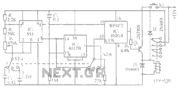
1-20 minutes a timing circuit
The system operates between 10 minutes to 2 hours, featuring a 100-line bell controlled by a multi-gear stick labeled S2 41f. The integrated circuit (IC) functions as a self-excited multivibrator. The device can manage binary pulses ranging from 3 to...