


Thermometer with a LM335
#LM335
#temperature sensor
#thermometer
#voltage output
#measurement
#calibration
#DVM
#degrees Celsius
#Kelvin
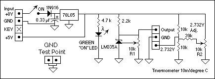
Description: The circuit consists of two parts: The LM335 and its adjustment. The output of the LM335 is 10 millivolts per degree C, with 25 degrees C corresponding to 2.982 VDC. A reference circuit provides a zero reference voltage. It is adjusted to (2.982 volts - (25 degrees x 10 millivolts/degree) = 2.832 volts. To read the temperature of the LM335 directly in degrees C, connect the + lead from a high impedance DVM to the output pin and the - end of the DVM to the 2.732 volt pin. The factor of 10 millivolts per degree C is equivalent to 10 millivolts per degree K, since a change of one degree C is equal to a change of one degree K. The difference in the two scales is only their offsets. The melting point of water ice is 0 degrees C and 273.15 degrees K. The boiling point of water is 100 degrees C and 373.15 degrees K. Calibration: Set the voltage at the "Output" pin to 2.982 volts when the LM335 is at 25 degrees C. Adjust R2 to obtain 2.732 volts at the 2.732V output - this second adjustment is (ideally) independent of temperature. If you can get your hands on metal film resistors for the 2.732 volt divider, so much the better. Otherwise, adjust the 2.732 volt reference at the ambient temperature in which the thermometer is intended to be used. Use a good quality pot for R1 because the circuit's calibration depends on it. I used a Beckman Helitrim pot, dug out of my junk box, as R1, because of this excellent mechanical stability with temperature change and well as a low thermal temperature coefficient of resistance. The LM335 is made by National Semiconductor and STMicroelectronics. I found the ones I bought at Arrow for only 65 cents each (plus the shipping charge). They can also be found for sale on the National Semiconductor website among others. I recommend the data sheet on the National Semiconductor site as the illustrations are clearer than those on the STMicroelectronics site.
The circuit described is a temperature measurement system utilizing the LM335 temperature sensor, which provides an output voltage linearly proportional to temperature. The output voltage of the LM335 is specified as 10 millivolts per degree Celsius. At a reference temperature of 25 degrees Celsius, the output voltage is calibrated to 2.982 VDC. This voltage serves as a baseline for temperature readings, and the circuit includes a reference circuit to establish a zero reference voltage, which is adjusted to 2.832 volts.
To directly measure the temperature in degrees Celsius, a high-impedance digital voltmeter (DVM) is employed. The positive lead of the DVM connects to the LM335 output pin, while the negative lead connects to the 2.732V reference output. This configuration allows for accurate temperature readings, as the output voltage is directly correlated to the temperature in degrees Celsius and Kelvin, with the understanding that the two scales differ only in their offsets.
Calibration of the circuit is critical for accurate temperature measurement. The initial step involves setting the output voltage at the "Output" pin to 2.982 volts when the LM335 is at the reference temperature of 25 degrees Celsius. Subsequently, a resistor, R2, is adjusted to achieve a voltage of 2.732 volts at the designated reference point. It is recommended that metal film resistors be used for the voltage divider to enhance accuracy, as they provide better stability and lower thermal coefficients compared to other resistor types.
The selection of components is also important for maintaining calibration stability. A high-quality potentiometer, such as a Beckman Helitrim pot, is suggested for R1 due to its mechanical stability under varying temperatures and low thermal coefficient of resistance. The choice of the LM335 sensor is significant, as it is available from reputable manufacturers like National Semiconductor and STMicroelectronics, ensuring reliability and performance.
In summary, this temperature sensor circuit, with its careful calibration and component selection, provides a reliable means of measuring temperature accurately in both Celsius and Kelvin, making it suitable for various applications where precise temperature monitoring is required.The circuit consists of two parts: The LM335 and its adjustment. The output of the LM335 is 10 millivolts per degree C, with 25 degrees C corresponding to 2.982 VDC. A reference circuit provides a zero reference voltage. It is adjusted to (2.982 volts - (25 degrees x 10 millivolts/degree) = 2.832 volts. To read the temperature of the LM335 directly in degrees C, connect the + lead from a high impedance DVM to the output pin and the - end of the DVM to the 2.732 volt pin. The factor of 10 millivolts per degree C is equivalent to 10 millivolts per degree K, since a change of one degree C is equal to a change of one degree K.
The difference in the two scales is only their offsets. The melting point of water ice is 0 degrees C and 273.15 degrees K. The boiling point of water is 100 degress C and 373.15 degrees K. Calibration: Set the voltage at the "Output" pin to 2.982 volts when the LM335 is at 25 degrees C. Adjust R2 to obtain 2.732 volts at the 2.732V output -this second adjustment is (ideally) independent of temperature. If you can get your hands on metal film resistors for the 2.732 volt divider, so much the better. Otherwise, adjust the 2.732 volt reference at the ambient temperature in which the thermometer is intended to be used.
Use a good quality pot for R1 because the circuit's calibration depends on it. I used a Beckman Helitrim pot, dug out of my junk box, as R1, because of this excellent mechanical stability with temperature change and well as a low thermal temperature coeficient of resistance. The LM335 is made by National Semiconductor and STMicroelectronics. I found the ones I bought at Arrow (http://www.arrow.com/) for only 65 cents each (plus the shipping charge).
They can also be found for sale on the National Semiconductor web site among others. I recommend the data sheet on the National Semiconductor site as the illustrations are clearer than those on the STMicroelectronics site.
The circuit described is a temperature measurement system utilizing the LM335 temperature sensor, which provides an output voltage linearly proportional to temperature. The output voltage of the LM335 is specified as 10 millivolts per degree Celsius. At a reference temperature of 25 degrees Celsius, the output voltage is calibrated to 2.982 VDC. This voltage serves as a baseline for temperature readings, and the circuit includes a reference circuit to establish a zero reference voltage, which is adjusted to 2.832 volts.
To directly measure the temperature in degrees Celsius, a high-impedance digital voltmeter (DVM) is employed. The positive lead of the DVM connects to the LM335 output pin, while the negative lead connects to the 2.732V reference output. This configuration allows for accurate temperature readings, as the output voltage is directly correlated to the temperature in degrees Celsius and Kelvin, with the understanding that the two scales differ only in their offsets.
Calibration of the circuit is critical for accurate temperature measurement. The initial step involves setting the output voltage at the "Output" pin to 2.982 volts when the LM335 is at the reference temperature of 25 degrees Celsius. Subsequently, a resistor, R2, is adjusted to achieve a voltage of 2.732 volts at the designated reference point. It is recommended that metal film resistors be used for the voltage divider to enhance accuracy, as they provide better stability and lower thermal coefficients compared to other resistor types.
The selection of components is also important for maintaining calibration stability. A high-quality potentiometer, such as a Beckman Helitrim pot, is suggested for R1 due to its mechanical stability under varying temperatures and low thermal coefficient of resistance. The choice of the LM335 sensor is significant, as it is available from reputable manufacturers like National Semiconductor and STMicroelectronics, ensuring reliability and performance.
In summary, this temperature sensor circuit, with its careful calibration and component selection, provides a reliable means of measuring temperature accurately in both Celsius and Kelvin, making it suitable for various applications where precise temperature monitoring is required.The circuit consists of two parts: The LM335 and its adjustment. The output of the LM335 is 10 millivolts per degree C, with 25 degrees C corresponding to 2.982 VDC. A reference circuit provides a zero reference voltage. It is adjusted to (2.982 volts - (25 degrees x 10 millivolts/degree) = 2.832 volts. To read the temperature of the LM335 directly in degrees C, connect the + lead from a high impedance DVM to the output pin and the - end of the DVM to the 2.732 volt pin. The factor of 10 millivolts per degree C is equivalent to 10 millivolts per degree K, since a change of one degree C is equal to a change of one degree K.
The difference in the two scales is only their offsets. The melting point of water ice is 0 degrees C and 273.15 degrees K. The boiling point of water is 100 degress C and 373.15 degrees K. Calibration: Set the voltage at the "Output" pin to 2.982 volts when the LM335 is at 25 degrees C. Adjust R2 to obtain 2.732 volts at the 2.732V output -this second adjustment is (ideally) independent of temperature. If you can get your hands on metal film resistors for the 2.732 volt divider, so much the better. Otherwise, adjust the 2.732 volt reference at the ambient temperature in which the thermometer is intended to be used.
Use a good quality pot for R1 because the circuit's calibration depends on it. I used a Beckman Helitrim pot, dug out of my junk box, as R1, because of this excellent mechanical stability with temperature change and well as a low thermal temperature coeficient of resistance. The LM335 is made by National Semiconductor and STMicroelectronics. I found the ones I bought at Arrow (http://www.arrow.com/) for only 65 cents each (plus the shipping charge).
They can also be found for sale on the National Semiconductor web site among others. I recommend the data sheet on the National Semiconductor site as the illustrations are clearer than those on the STMicroelectronics site.
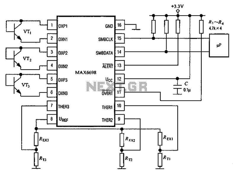
With a 7-Channel Smart Temperature Sensor MAX6698 circuit diagram
Channel 7 presents a circuit diagram of a smart temperature sensor using the MAX6698. This circuit includes three transistors (VT1, VT2, and VT3) and three thermistors (RT1, RT2, and RT3). An internal reference voltage source is provided via resistors (UREF...
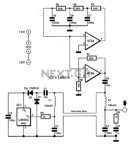
Temperature measurement using two cables
In situations where temperature measurement is required in a remote area, an imaging unit is installed, necessitating a connection to the appropriate sensor. The most commonly used cables typically consist of three conductors: two for powering the sensor and one...
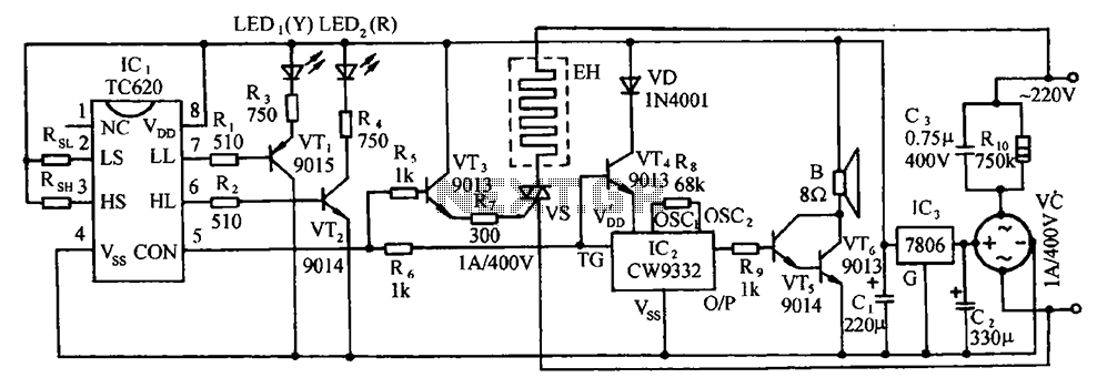
TC620 temperature sensor circuit diagram of automatic heating temperature control
The circuit includes the TC620 temperature control circuit, the temperature indicator circuit, a thyristor-controlled heating circuit, a vocal music buck rectifier circuit, and the AC circuit.
The TC620 temperature control circuit is designed to regulate temperature by monitoring the temperature sensor...
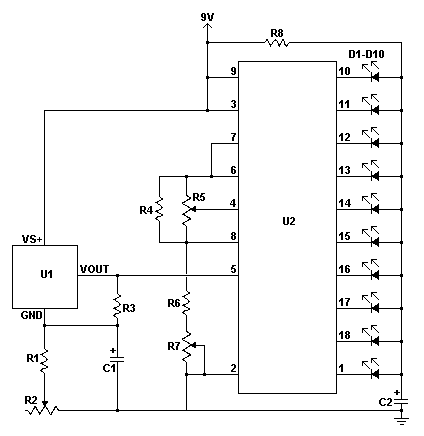
Thermometer with 10 LED scale
This LED thermometer is designed for in home use, to read temperatures between about 60 and 78 degrees Fahrenheit. It is based around a precision temperature sensor IC, the LM34DZ. This sensor require no calibration and can measure temperatures of...
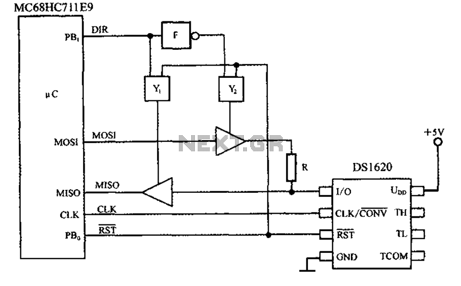
Intelligent interface circuit and temperature sensor DS1620 SPI bus circuit
This circuit features a three-wire serial interface for smart temperature sensors, specifically the DS1620, along with an SPI bus interface circuit.
The DS1620 is a high-accuracy digital temperature sensor that communicates over a three-wire interface, which consists of a data line...

digital remote thermometer
The frequency pulses originating from the mains supply are safely insulated by capacitors C1 and C2, along with inductor L1. These pulses are amplified by transistor Q1, while diodes D1 and D2 limit any peak voltages at the input. The...

Leak Detector
High sensitivity, portable temperature comparator. This sensitive circuit is basically a comparator, detecting very slight temperature changes in respect to the ambient temperature. It was primarily intended to detect draughts around doors and windows that cause energy leaks but can...
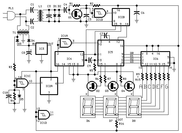
Digital Remote Thermometer
This circuit is designed for precise centigrade temperature measurement. It includes a transmitter section that converts the sensor's output voltage, which is proportional to the measured temperature, into frequency. The output frequency bursts are transmitted through the mains supply cables....
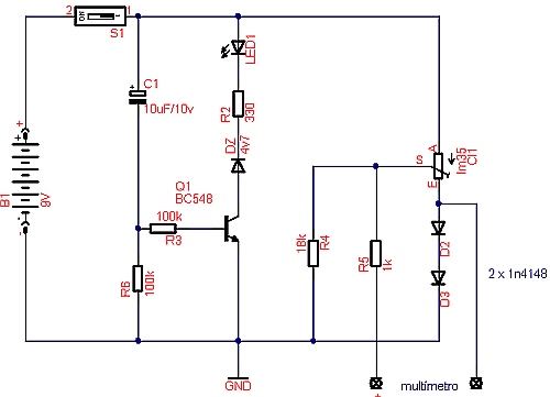
Module thermometer temperature meter for digital multimeter using the ic lm35
Temperature sensor converter designed for use with a digital multimeter, capable of measuring temperatures from -40 °C to 110 °C. It features a state indicator and requires no calibration, utilizing the LM35 integrated circuit. The freezing point of water is...