


Touch Screen Model
#touch screen
#capacitive
#sensor
#user interface
#transparent conductors
#physical modeling
#touch detection
#electronics
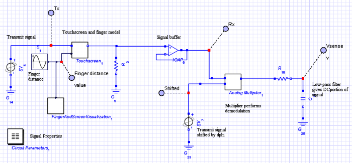
Description: The objective of this project is to develop a model of a capacitive touch screen, which includes the physical modeling of a user's finger, the materials of the touch screen, and the touch-detection circuitry. A capacitive touch screen functions by measuring the change in capacitance between two conductors caused by the proximity of a finger. In the touch screen, two transparent conductors, arranged in perpendicular directions, are separated by the screen. These conductors form a parallel-plate capacitor where they overlap; the capacitance is influenced by various physical parameters. Factors such as the width, length, resistivity, and separation of the conductors, along with the properties and thickness of the screen material, all impact the coupling between the conductors. To operate a single pixel of the touch screen, a specific frequency is transmitted along one conductor and received by the other. The capacitive coupling between the conductors results in a particular phase shift in the received signal. When a finger approaches the area where the conductors overlap, it alters the capacitance between them, as the finger acts as a ground reference. This induces an additional phase shift, which is detected by a simple demodulator circuit and converted into a DC signal. When this DC signal surpasses a defined threshold, a touch is recognized by the pixel. This process is repeated for all pixels on the touch screen to ascertain which locations are being activated. The conventional method for modeling a touch screen relies on a purely circuit-based design that necessitates precomputed component values from another environment. Adjustments to the design parameters would entail recalculating and re-entering these values into the circuit model before running subsequent simulations, rendering experimentation and refinement of the model challenging and time-consuming. For instance, the coupling capacitance between the transmitting and receiving conductors must be calculated in advance and input into the circuit simulation. Likewise, the effect of a grounded finger must be modeled as a time-dependent capacitance with a predetermined time-domain waveform loaded into the simulator. Additionally, the demodulator, which essentially multiplies two sine waves, must be constructed using a complete demodulator circuit rather than simply multiplying two signals.
The capacitive touch screen model described involves a sophisticated interplay of physical and electrical parameters. The primary components include the transparent conductors, which are typically made from materials such as indium tin oxide (ITO) due to their excellent conductivity and transparency. The arrangement of these conductors is critical, as their perpendicular orientation maximizes the area of overlap, thereby enhancing the sensitivity of the touch screen.
The modeling of a user's finger is crucial, as it introduces a variable capacitance that significantly affects the overall performance of the touch screen. The finger's proximity alters the electric field between the conductors, effectively changing the capacitance and leading to the phase shift detected by the circuitry. The demodulation process is essential for translating the phase shift into a usable signal. A typical demodulator circuit may utilize operational amplifiers to process the incoming signals, ensuring that the variations in capacitance due to touch are accurately converted into a digital signal that can be interpreted by a microcontroller.
To optimize the design, advanced simulation tools can be employed to model the capacitive interactions dynamically. These tools can facilitate real-time adjustments to parameters such as conductor spacing, material properties, and signal frequencies, enabling a more responsive design process. By implementing a feedback loop within the simulation, designers can iteratively refine the touch screen model based on performance metrics derived from initial tests, thereby enhancing the accuracy and reliability of touch detection.
In conclusion, the development of a capacitive touch screen model involves a comprehensive understanding of both the electrical and physical aspects of the system. By leveraging advanced modeling techniques and circuit design principles, it is possible to create a highly responsive and accurate touch interface suitable for a wide range of applications.The challenge of this project is to create a model of a capacitive touch screen, including physical modeling of a user`s finger, the touch screen materials, and the touch-detection circuitry. A capacitive touch screen works by measuring the change in capacitance between two conductors caused by a nearby finger.
In the touch screen, two transparent conductors, which run in perpendicular directions, are separated by the screen. These conductors act as a parallel-plate capacitor where they overlap; the capacitance is determined by numerous physical parameters. For example, the conductor width, length, resistivity, and separation, along with the screen material properties and thickness, all affect the coupling between the conductors.
To operate a single pixel of the touch screen, a particular frequency is transmitted along one conductor and received by the other. The capacitive coupling between the conductors causes a particular phase shift in the received signal.
When a finger is close enough to where the conductors overlap, it changes the capacitance between the conductors because the finger appears to be grounded. This causes an additional phase shift, which is detected by a simple demodulator circuit and converted into a DC signal.
When the DC signal exceeds a given threshold, a touch is detected by the pixel. This process occurs for all of the touch screen pixels to determine which locations are being touched. The traditional approach to modeling a touch screen uses a purely circuit-based design that uses components whose values must be precomputed in another environment.
Changes in the design parameters would require the recalculation and re-entry of these and other values into the circuit model before subsequent simulations; this process makes experimentation and fine-tuning of the model difficult and time-consuming. For example, the coupling capacitance between the transmitting and receiving conductors would have to be calculated and fed into the circuit simulation ahead of time.
Similarly, the effect of a grounded finger would have to be incorporated as some time-dependent capacitance whose time-domain waveform is predetermined and loaded into the simulator. Also, the demodulator, which is essentially the multiplication of two sine waves, would have to be implemented using a full demodulator circuit as opposed to simply multiplying two signals.
The capacitive touch screen model described involves a sophisticated interplay of physical and electrical parameters. The primary components include the transparent conductors, which are typically made from materials such as indium tin oxide (ITO) due to their excellent conductivity and transparency. The arrangement of these conductors is critical, as their perpendicular orientation maximizes the area of overlap, thereby enhancing the sensitivity of the touch screen.
The modeling of a user's finger is crucial, as it introduces a variable capacitance that significantly affects the overall performance of the touch screen. The finger's proximity alters the electric field between the conductors, effectively changing the capacitance and leading to the phase shift detected by the circuitry. The demodulation process is essential for translating the phase shift into a usable signal. A typical demodulator circuit may utilize operational amplifiers to process the incoming signals, ensuring that the variations in capacitance due to touch are accurately converted into a digital signal that can be interpreted by a microcontroller.
To optimize the design, advanced simulation tools can be employed to model the capacitive interactions dynamically. These tools can facilitate real-time adjustments to parameters such as conductor spacing, material properties, and signal frequencies, enabling a more responsive design process. By implementing a feedback loop within the simulation, designers can iteratively refine the touch screen model based on performance metrics derived from initial tests, thereby enhancing the accuracy and reliability of touch detection.
In conclusion, the development of a capacitive touch screen model involves a comprehensive understanding of both the electrical and physical aspects of the system. By leveraging advanced modeling techniques and circuit design principles, it is possible to create a highly responsive and accurate touch interface suitable for a wide range of applications.The challenge of this project is to create a model of a capacitive touch screen, including physical modeling of a user`s finger, the touch screen materials, and the touch-detection circuitry. A capacitive touch screen works by measuring the change in capacitance between two conductors caused by a nearby finger.
In the touch screen, two transparent conductors, which run in perpendicular directions, are separated by the screen. These conductors act as a parallel-plate capacitor where they overlap; the capacitance is determined by numerous physical parameters. For example, the conductor width, length, resistivity, and separation, along with the screen material properties and thickness, all affect the coupling between the conductors.
To operate a single pixel of the touch screen, a particular frequency is transmitted along one conductor and received by the other. The capacitive coupling between the conductors causes a particular phase shift in the received signal.
When a finger is close enough to where the conductors overlap, it changes the capacitance between the conductors because the finger appears to be grounded. This causes an additional phase shift, which is detected by a simple demodulator circuit and converted into a DC signal.
When the DC signal exceeds a given threshold, a touch is detected by the pixel. This process occurs for all of the touch screen pixels to determine which locations are being touched. The traditional approach to modeling a touch screen uses a purely circuit-based design that uses components whose values must be precomputed in another environment.
Changes in the design parameters would require the recalculation and re-entry of these and other values into the circuit model before subsequent simulations; this process makes experimentation and fine-tuning of the model difficult and time-consuming. For example, the coupling capacitance between the transmitting and receiving conductors would have to be calculated and fed into the circuit simulation ahead of time.
Similarly, the effect of a grounded finger would have to be incorporated as some time-dependent capacitance whose time-domain waveform is predetermined and loaded into the simulator. Also, the demodulator, which is essentially the multiplication of two sine waves, would have to be implemented using a full demodulator circuit as opposed to simply multiplying two signals.
Scoobas Solution Sensing Tactic
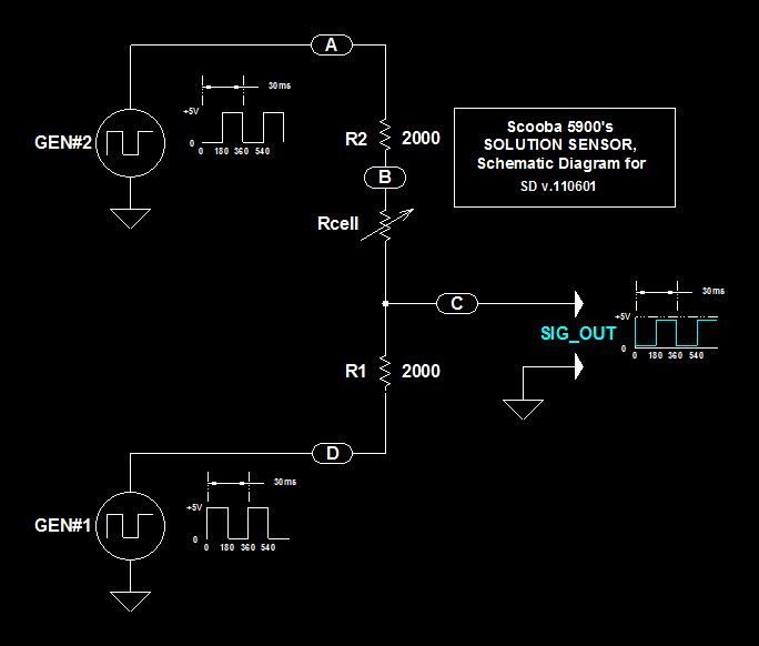
This document serves multiple purposes, primarily to document the methods employed by a Scooba robot to detect: a) the presence of an acceptable cleaning solution being delivered to its pump, and b) the excess presence of used solution collected off...
Sensor-Activated Relay Pulser Circuit
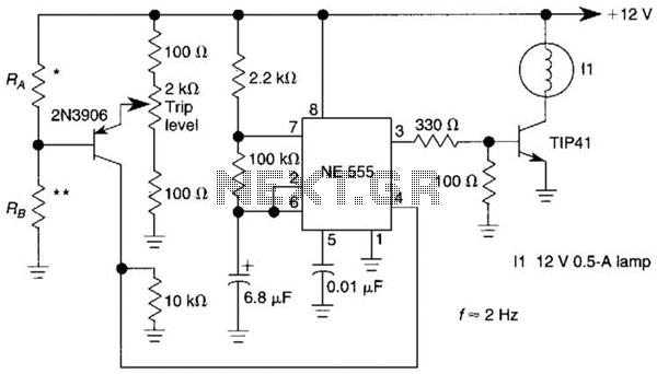
A sensor activates transistor Q1 to turn on the low-frequency 555 oscillator, which generates pulses to control LAMP II. The sensor may respond to variations in light or temperature. Either resistor RA or RB can function as the sensor, depending...
Add a sensor to a board and measure something with it
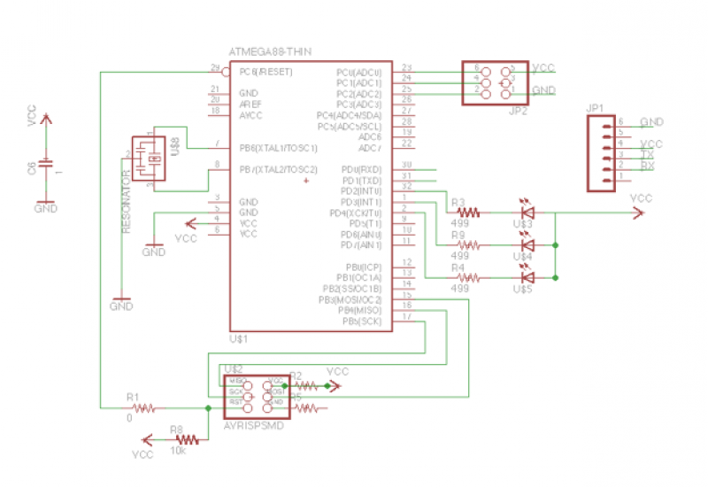
This week's plan is to build a device that warns of the potential for a knockdown, which is the process by which an over-canvassed ship is laid over on her beam-ends. The risk of sinking is high during this event,...
Capacitive Sensors
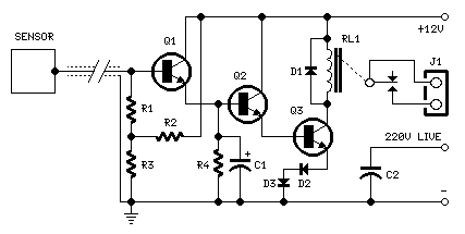
For proper operation, the circuit ground must be connected through a small-value, high-voltage-rated capacitor to one side of the mains supply socket. The "Live" side is the right one. This circuit is designed to animate shop windows using a capacitive...
Electronics Projects Circuits
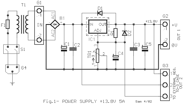
Over 1400 top electronics projects and electronic circuits with photos, datasheets, and easy-to-read schematics, along with explanations of how they work and how to build them.
The collection comprises a vast array of electronics projects suitable for enthusiasts and professionals alike....
Automatic Room light Control With Bi Directional Visitor Counter
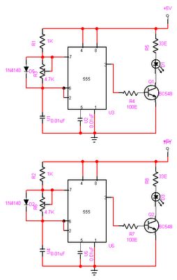
The objective of this project is to create a controller-based model that counts the number of individuals entering a specific room and activates the lighting accordingly. This is achieved through the use of sensors that detect the current number of...
Capacitive level measuring circuit
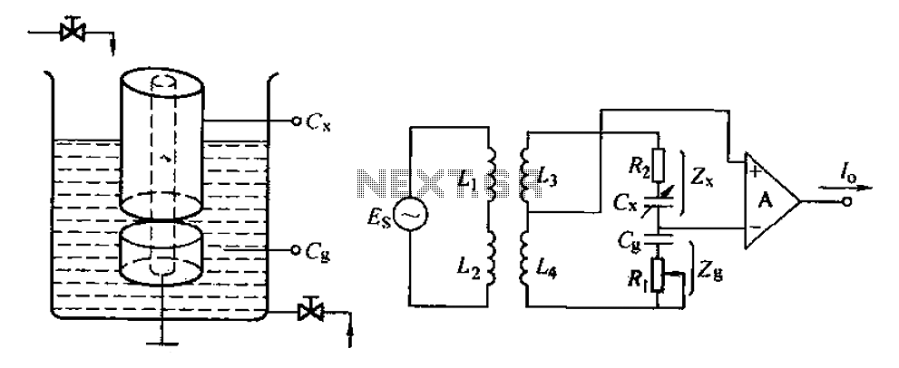
The capacitance change in a capacitive sensor is directly converted into electrical parameters, which are then unified for signal transmission, processing, and display. These electrical parameters can be categorized into resistive, capacitive, and inductive types. This explanation focuses on capacitive...
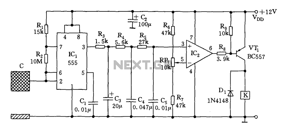
Capacitive switch circuit diagram
The switch circuit consists of a capacitive oscillator, an integration network, and a comparator circuit that controls a relay. When a body comes close to the induction plate, the inductive capacitance to ground increases, causing the 555 astable multivibrator to...
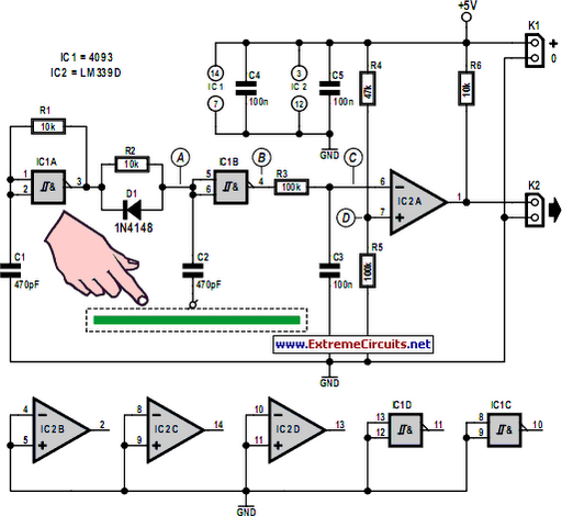
Simple Capacitive Touch Sensor
Capacitive touch sensors operate based on the electrical capacitance of the human body. When a finger approaches the sensor, it establishes a capacitance to Earth ranging from 30 to 100 pF. This phenomenon can be utilized for proximity detection and...