


Water Activated Relay
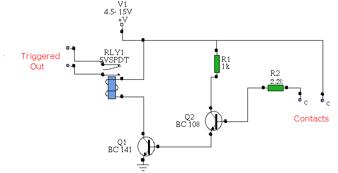
Description: In this circuit, two transistors are configured as a high-gain compound pair. Transistor T1 is likely a 2N2222A, while T2 is identified as a BC108. The current gain is calculated as the product of the beta values of each transistor, which has a minimum of 140 for T1 and 110 for T2, resulting in a current gain of 15,400. The power supply can range from 4.5 to 15 volts. A typical 5-volt relay may require 60 mA to operate, meaning that any fluid conducting a minimum current of 4 µA will activate the relay. This level of current can be easily achieved with tap or rainwater.
The described circuit utilizes two transistors, T1 (2N2222A) and T2 (BC108), arranged in a compound configuration to enhance the overall current gain significantly. The 2N2222A is a popular NPN transistor known for its versatility and robustness, while the BC108 is a general-purpose NPN transistor that complements the 2N2222A in this application. The high gain of 15,400 indicates that even a small input current can be amplified to a much larger output current, making the circuit highly sensitive to small variations in input.
The design allows for a power supply voltage ranging from 4.5 to 15 volts, providing flexibility for various applications. The choice of a 5-volt relay, which typically requires 60 mA to activate, indicates that the circuit can be effectively used in low-power applications where the relay serves as a switch for controlling larger loads. The ability to activate the relay with a minimum input current of 4 µA signifies that the circuit is suitable for use with conductive fluids, such as tap or rainwater, which can easily provide the necessary current.
This circuit can be employed in applications such as liquid level sensing or fluid detection systems, where the presence of a conductive liquid can trigger a relay to control pumps, alarms, or other devices. The high sensitivity and low activation current make it ideal for monitoring systems that require minimal power consumption and reliable operation. Proper biasing and stabilization of the transistors are essential to ensure consistent performance, and additional components such as resistors and capacitors may be included in the schematic to enhance stability and response time.In his circuit Marin has used two transistors wired as a high gain compound pair. Transistor T1 may be a 2N2222A and T2 a BC108. The current gain will be the product of each transistors beta, which will be a minimum of 140 x 110 or 15400. The power supply used can be any voltage from 4. 5 to 15 volts, a typical 5 volt relay may require 60 mA to operate, in which case any fluid which passes a minimum current of 4 uA will activate the relay. This is easily achieved with tap or rain water.
The described circuit utilizes two transistors, T1 (2N2222A) and T2 (BC108), arranged in a compound configuration to enhance the overall current gain significantly. The 2N2222A is a popular NPN transistor known for its versatility and robustness, while the BC108 is a general-purpose NPN transistor that complements the 2N2222A in this application. The high gain of 15,400 indicates that even a small input current can be amplified to a much larger output current, making the circuit highly sensitive to small variations in input.
The design allows for a power supply voltage ranging from 4.5 to 15 volts, providing flexibility for various applications. The choice of a 5-volt relay, which typically requires 60 mA to activate, indicates that the circuit can be effectively used in low-power applications where the relay serves as a switch for controlling larger loads. The ability to activate the relay with a minimum input current of 4 µA signifies that the circuit is suitable for use with conductive fluids, such as tap or rainwater, which can easily provide the necessary current.
This circuit can be employed in applications such as liquid level sensing or fluid detection systems, where the presence of a conductive liquid can trigger a relay to control pumps, alarms, or other devices. The high sensitivity and low activation current make it ideal for monitoring systems that require minimal power consumption and reliable operation. Proper biasing and stabilization of the transistors are essential to ensure consistent performance, and additional components such as resistors and capacitors may be included in the schematic to enhance stability and response time.In his circuit Marin has used two transistors wired as a high gain compound pair. Transistor T1 may be a 2N2222A and T2 a BC108. The current gain will be the product of each transistors beta, which will be a minimum of 140 x 110 or 15400. The power supply used can be any voltage from 4. 5 to 15 volts, a typical 5 volt relay may require 60 mA to operate, in which case any fluid which passes a minimum current of 4 uA will activate the relay. This is easily achieved with tap or rain water.
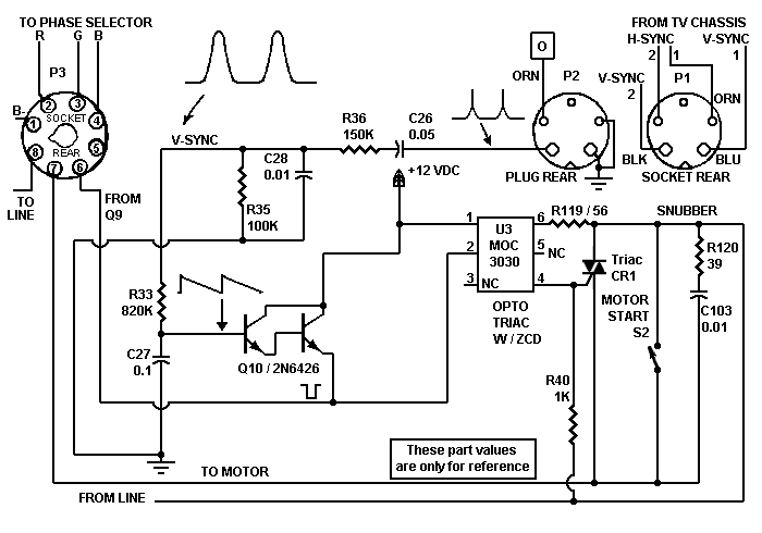
TRANSISTOR MOTOR CONTROLLER
Despite the high impedance of its inputs, the Darlington transistor Q10 generates sufficient current to drive an LED. The inverted output of Q10 powers the internal LED of opto isolator U5, which, in turn, couples to the motor control triac...
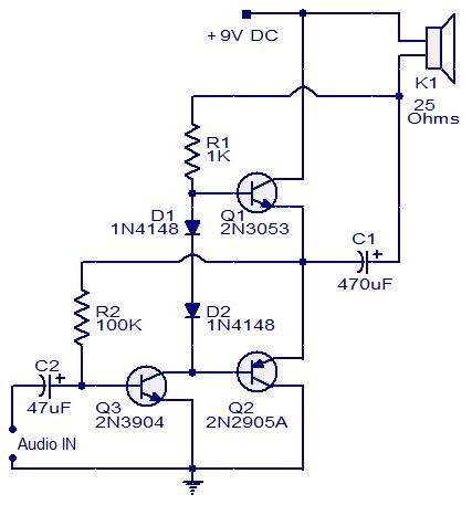
Three transistor audio amplifier
This circuit diagram illustrates a simple three-transistor audio amplifier capable of delivering approximately 100 mW of power to a 25 Ohm speaker. Diodes D1 and D2 provide a constant bias voltage for transistors Q1 and Q2. Transistor Q1 functions as...

Amplitude separation circuit diagram
Amplitude separation circuit. A typical amplitude separating circuit is composed of a transistor, capacitance C, and resistances RB and RC. The input signal is a composite video signal, typically with a peak-to-peak voltage of about 2V. The output signal is...
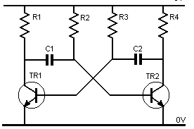
transistor astable multivibrator
Assume one of the transistors, TR1, becomes conductive initially. Under this condition, the collector-emitter voltage of TR1 should ideally be zero; however, it will be approximately 0.1 volts, while the base-emitter voltage is +0.6 volts. As a result, capacitor C1...
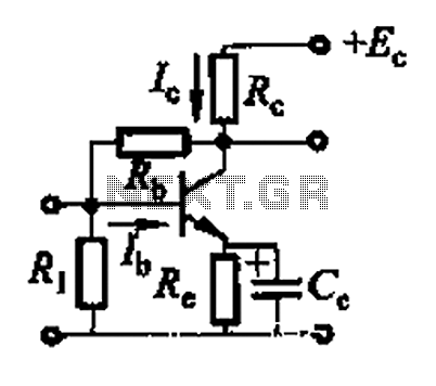
Basic reference transistor bias circuit - Mixed Negative feedback
Basic reference transistor bias circuit - Mixed Negative feedback
The basic reference transistor bias circuit utilizing mixed negative feedback is a fundamental electronic configuration designed to stabilize the operating point of a transistor. This circuit typically employs a combination of resistive...
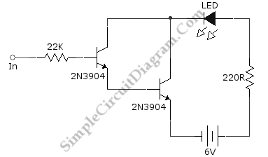
Darlington Transistor Pair Logic Probe
Ideally, any testing equipment will not draw any current from the device under test. This ideal condition can be approximated by designing a testing device.
To achieve the ideal condition where testing equipment does not draw current from the device under...
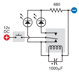
relay circuit
The intended result is for the relay to oscillate and the LEDs to flash when the button is pressed. However, when the button is pressed, the leftmost LED lights constantly, and nothing else happens. There is voltage across the left...
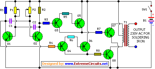
Inverter Circuit For Soldering Iron circuit
This is a simple and cost-effective inverter designed to power a small soldering iron (25W, 35W, etc.) when a mains supply is not available. The circuit utilizes eight transistors along with several resistors and capacitors. Transistors Q1 and Q2, both...
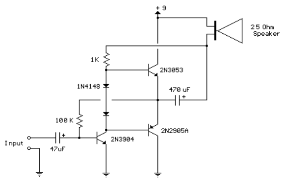
3 transistor audio amp 80 milliwatt
This circuit is similar to the previous one but employs positive feedback to enhance the amplitude delivered to the speaker. It was derived from a small 5-transistor radio utilizing a 25-ohm speaker. In the previous circuit, the load resistor for...