


Water Activated Relay circuit board
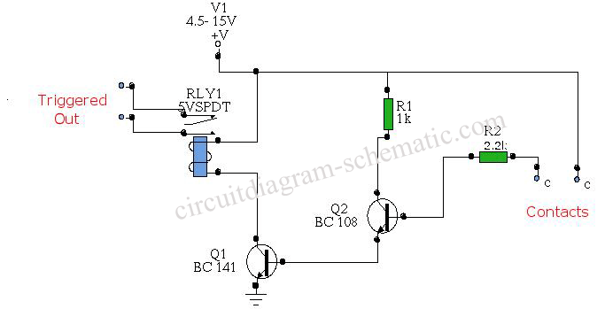
Description: The circuit diagram represents a water-activated relay circuit. This circuit employs two transistors configured as a high-gain compound pair. The transistors used are 2N2222A for T1 and T2, which may also be substituted with BC108. The current gain is determined by the product of each transistor's beta, which has a minimum value of 140 for T1 and 110 for T2, resulting in a total gain of 15,400. The power supply voltage can range from 4.5 to 15 volts, with a typical value being 5 volts. A standard relay may require 60 mA to operate, and in this scenario, any fluid flow that generates at least 4 microamperes (UA) will activate the relay. This activation can be easily achieved using tap water or rainwater. The following is a schematic drawing:
The water-activated relay circuit utilizes a simple yet effective design to control devices based on the presence of water. The primary components include two transistors, which serve as the core amplification elements. The first transistor (T1), a 2N2222A, is configured in a common-emitter arrangement, providing a significant voltage gain and enabling the circuit to respond to low currents generated by water flow. The second transistor (T2), also a 2N2222A or a BC108, operates in a similar manner, enhancing the overall current gain of the circuit.
The circuit is powered by a DC voltage supply, typically set at 5 volts for optimal performance. This voltage level is sufficient to drive the relay, which generally requires a current of 60 mA to engage its switching mechanism. The relay serves as the output device, allowing the circuit to control larger loads, such as lights or pumps, based on the water detection input.
The water detection mechanism relies on the conductivity of water, which allows a small current to flow through the circuit when water is present. This current is sufficient to bias the transistors into their active regions, enabling them to amplify the current and ultimately energize the relay coil. The threshold for activation is set at a minimum of 4 microamperes, which can be easily achieved with common sources of water, such as tap water or rainwater.
In summary, this water-activated relay circuit is a practical solution for applications requiring automatic control based on water presence. Its design leverages the high gain characteristics of the transistors to ensure reliable operation with minimal water flow, making it suitable for various environmental monitoring and automation tasks.Circuit diagram is water activated relay circuit. In this diagram circuit using two transistors connected as a high gain compound pair. 2N2222A transistors T1 and T2 may be a BC108. Current gain will be the product of each transistor beta, which will be a minimum of 140 x 110 or 15, 400. Power supply voltage can be used 4, 5-15 volts, a typical 5-vo lt relay may require 60 mA to operate, in this case any fluid flow through at least 4 UA will activate the relay. This is easily achieved with tap or rain water. The following is a schematic drawing:
The water-activated relay circuit utilizes a simple yet effective design to control devices based on the presence of water. The primary components include two transistors, which serve as the core amplification elements. The first transistor (T1), a 2N2222A, is configured in a common-emitter arrangement, providing a significant voltage gain and enabling the circuit to respond to low currents generated by water flow. The second transistor (T2), also a 2N2222A or a BC108, operates in a similar manner, enhancing the overall current gain of the circuit.
The circuit is powered by a DC voltage supply, typically set at 5 volts for optimal performance. This voltage level is sufficient to drive the relay, which generally requires a current of 60 mA to engage its switching mechanism. The relay serves as the output device, allowing the circuit to control larger loads, such as lights or pumps, based on the water detection input.
The water detection mechanism relies on the conductivity of water, which allows a small current to flow through the circuit when water is present. This current is sufficient to bias the transistors into their active regions, enabling them to amplify the current and ultimately energize the relay coil. The threshold for activation is set at a minimum of 4 microamperes, which can be easily achieved with common sources of water, such as tap water or rainwater.
In summary, this water-activated relay circuit is a practical solution for applications requiring automatic control based on water presence. Its design leverages the high gain characteristics of the transistors to ensure reliable operation with minimal water flow, making it suitable for various environmental monitoring and automation tasks.Circuit diagram is water activated relay circuit. In this diagram circuit using two transistors connected as a high gain compound pair. 2N2222A transistors T1 and T2 may be a BC108. Current gain will be the product of each transistor beta, which will be a minimum of 140 x 110 or 15, 400. Power supply voltage can be used 4, 5-15 volts, a typical 5-vo lt relay may require 60 mA to operate, in this case any fluid flow through at least 4 UA will activate the relay. This is easily achieved with tap or rain water. The following is a schematic drawing:
relay tutorial
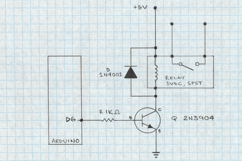
A relay is an electromechanical switch that operates by opening and closing under the control of another electric circuit. When current flows through the relay's coil, a magnetic field is generated, causing an armature to move, which either establishes or...

rising pitch siren
A two-transistor electronic siren breadboard circuit that produces an audible rising pitch on a loudspeaker. This circuit serves as a tutorial for beginners in electronics.
The two-transistor siren circuit operates by utilizing the properties of transistors to create an oscillating signal...

relay found in switch mode power supply
In the example above, a low voltage (12V DC) is utilized to activate a relay that switches a 240V AC main circuit. It is important to note that there is no electrical connection between the two circuits within the relay;...
transistors Mystery circuit: latching relay control with transitor / capacitor why doesnt it work
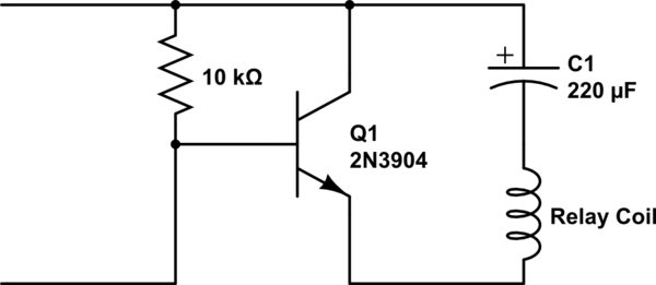
A single-coil latching relay is utilized, which can latch and reset with opposite polarities. Testing of the circuit with dual opposite-biased LEDs showed no flickering in either direction, indicating stable charge and discharge behavior. However, there are concerns regarding the...
Water Sensor Alarm Circuit
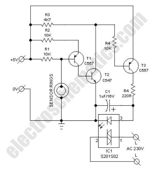
This compact water sensor alarm circuit emits a loud warning sound when a humidity sensor detects the presence of water. The circuit utilizes the low-power comparator LM1801 from National Semiconductor. A fixed reference voltage for the integrated circuit is established...
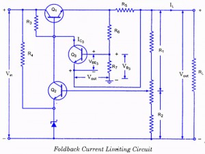
Controlled Transistor Series Regulator With Overload and Short-Circuit Protection
If the load resistance (RL) is reduced or the load terminals are accidentally shorted, a very large load current will flow, potentially damaging the pass transistor (Q1), diode, or other components. Fuse protection may not be sufficient, as the transistor...
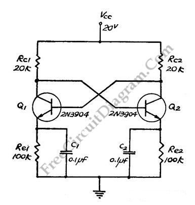
Direct Coupled Discrete Astable Multivibrator circuit
This flip-flop circuit functions as a free-running astable multivibrator, where the bases and collectors of both emitter-biased transistors are directly coupled. The switching action is facilitated by a capacitor in each emitter circuit, resulting in the generation of triangle waves...
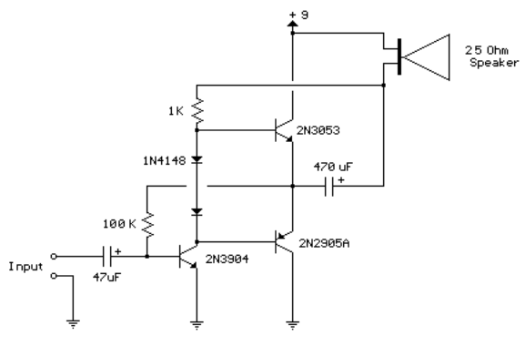
3 transistor audio amp 80 milliwatt
This circuit is similar to the previous one but employs positive feedback to enhance the amplitude delivered to the speaker. It was derived from a small 5-transistor radio utilizing a 25-ohm speaker. In the previous circuit, the load resistor for...
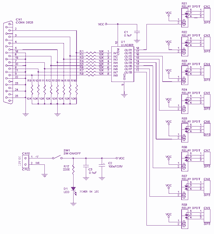
8 Channel LPT relay board
Channel Relay Board is a simple and convenient way to interface 8 relays for switching application in your project. Input - 12 VDC @ 336 mA. Output - eight SPDT relay. Relay specification - 5 A @ 230 VAC. Trigger...