


Water quality checker project simple circuit diagram
#water quality
#LDR
#measurement
#purity checker
#electronics project
#sensor circuit
#water testing
#light sensor
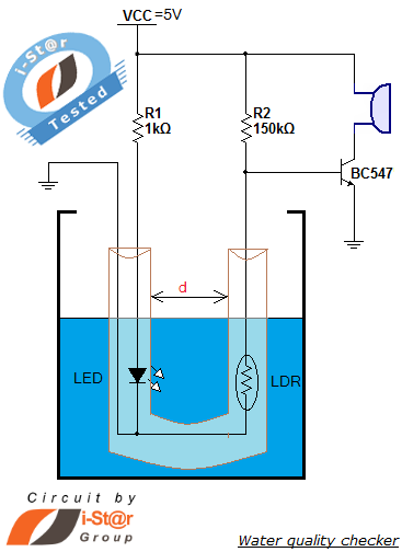
Description: How to measure water purity and test water quality using a simple electronics project. Water purity measurement and water quality analysis can be performed using a water purity checker circuit. This circuit is constructed around a Light Dependent Resistor (LDR) and several discrete components. A notable feature of this water purity tester is that it emits a beep sound when the water purity level falls below a specified threshold. This simple electronic project can be implemented in domestic water tanks for monitoring and testing water quality. The article provides a detailed circuit diagram and construction details for the water quality testing device. Additionally, it can be integrated with a previous circuit for a water tank level controller, resulting in an advanced engineering project. When the amount of mud in the water reservoir exceeds a threshold value, the water quality testing equipment produces a beep sound to alert users that the mud quantity has increased and requires cleaning.
The water purity checker circuit utilizes an LDR, which changes its resistance based on the light intensity that passes through the water. When water is clear, more light reaches the LDR, resulting in lower resistance. Conversely, as the water becomes increasingly contaminated, the turbidity increases, reducing the amount of light that reaches the LDR and causing its resistance to rise. This change in resistance can be converted into a voltage signal using a voltage divider circuit, which can then be monitored by a microcontroller or a simple comparator circuit.
To implement this project, the circuit typically includes a power supply, the LDR, a resistor for the voltage divider, a comparator (such as an operational amplifier), and a piezo buzzer for the alert sound. The comparator is set up to trigger when the voltage from the LDR exceeds a predetermined threshold, indicating poor water quality. When this condition is met, the comparator output activates the piezo buzzer, providing an audible alert.
For practical applications, the circuit can be housed in a waterproof enclosure to ensure durability and reliability in a wet environment. Calibration may be necessary to adjust the threshold according to specific water quality standards. The integration with a water tank level controller can enhance the functionality, allowing for simultaneous monitoring of both water purity and level, making it a comprehensive solution for water management in domestic settings. This project not only serves as a useful tool for ensuring water quality but also provides an educational opportunity for understanding basic electronics and environmental monitoring.How to measure water purity How to test water quality using a simple electronics project You can perform water purity measurement and water quality analysis using this water purity checker circuit. This circuit is built around a simple LDR (Light Depended Resistor) and some discrete components. The most attractive feature of our water purity tes ter is that it gives a beep sound when the water purity level goes below a threshold value. You can implement this simple electronic project in your domestic water tank for water quality monitoring and testing. The detailed circuit diagram and constructional details of water quality testing device are given in this article.
Also you can integrate this with our previous circuit of water tank level controller, the resulting circuit will be an advanced engineering project. When the amount of mud in the water reservoir exceeds a threshold value, our water quality testing equipment starts producing a beep sound to alert us that the quantity of mud in the water has increased and needs a cleaning.
The water purity checker circuit utilizes an LDR, which changes its resistance based on the light intensity that passes through the water. When water is clear, more light reaches the LDR, resulting in lower resistance. Conversely, as the water becomes increasingly contaminated, the turbidity increases, reducing the amount of light that reaches the LDR and causing its resistance to rise. This change in resistance can be converted into a voltage signal using a voltage divider circuit, which can then be monitored by a microcontroller or a simple comparator circuit.
To implement this project, the circuit typically includes a power supply, the LDR, a resistor for the voltage divider, a comparator (such as an operational amplifier), and a piezo buzzer for the alert sound. The comparator is set up to trigger when the voltage from the LDR exceeds a predetermined threshold, indicating poor water quality. When this condition is met, the comparator output activates the piezo buzzer, providing an audible alert.
For practical applications, the circuit can be housed in a waterproof enclosure to ensure durability and reliability in a wet environment. Calibration may be necessary to adjust the threshold according to specific water quality standards. The integration with a water tank level controller can enhance the functionality, allowing for simultaneous monitoring of both water purity and level, making it a comprehensive solution for water management in domestic settings. This project not only serves as a useful tool for ensuring water quality but also provides an educational opportunity for understanding basic electronics and environmental monitoring.How to measure water purity How to test water quality using a simple electronics project You can perform water purity measurement and water quality analysis using this water purity checker circuit. This circuit is built around a simple LDR (Light Depended Resistor) and some discrete components. The most attractive feature of our water purity tes ter is that it gives a beep sound when the water purity level goes below a threshold value. You can implement this simple electronic project in your domestic water tank for water quality monitoring and testing. The detailed circuit diagram and constructional details of water quality testing device are given in this article.
Also you can integrate this with our previous circuit of water tank level controller, the resulting circuit will be an advanced engineering project. When the amount of mud in the water reservoir exceeds a threshold value, our water quality testing equipment starts producing a beep sound to alert us that the quantity of mud in the water has increased and needs a cleaning.
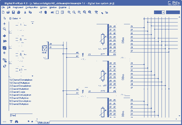
Digital-ProfiLab 4.0
Digital-ProfiLab was designed for measurement and control applications, combining features like circuit and logic simulation, front panel design, and hardware control to one powerful tool. Incoming signals from external devices may be processed and displayed. A circuit editor is used...
Light Follower Robot
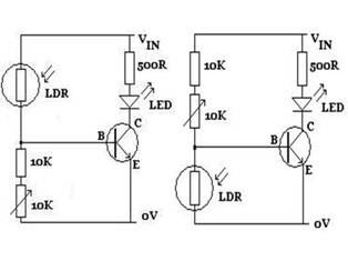
The figures above illustrate the fundamental concept of a robot, which consists of various input and output devices connected to a central processing unit, commonly referred to as the brain. These inputs and outputs are essential for the robot's functionality...
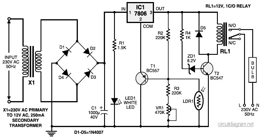
automatic light controller circuit diagram
During nighttime, when no light falls on LDR1, it offers a high resistance at the base junction of transistor T1. Consequently, the bias is significantly reduced, and T1 does not conduct. This effectively removes the common terminal of IC1 from...
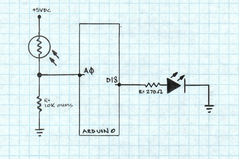
Arduino Light Sensors
A project is underway to determine the number of sun hours available at a specific location and to track this data over time as part of solar power installation design. The concept involves utilizing a light detector exposed to sunlight...
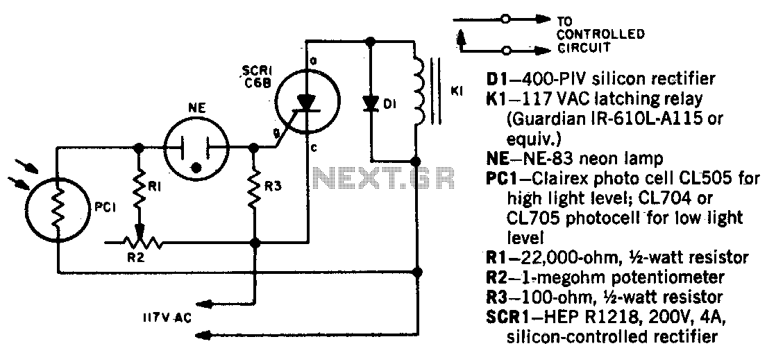
Light beam operated on-off relay
When a beam of light strikes the photocell, the voltage across the neon lamp NE-1 rises sharply. NE-1 turns on and triggers the SCR. K1 is an impulse relay whose contacts remain in position even after the coil current is...
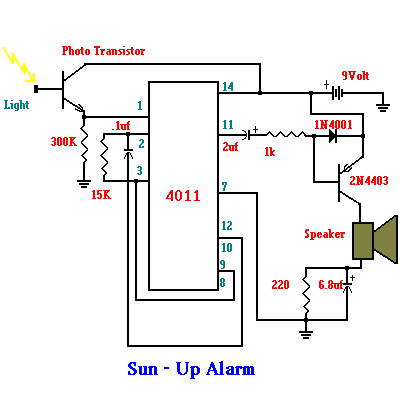
sun up alarm schematics
The Up Alarm is designed to provide an audible alert when sunlight is detected or when a light source is activated in a dark environment. It can also be utilized to sense various light sources such as beams or headlights....
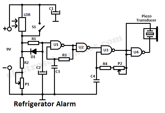
Refrigerator Alarm Circuit
When light strikes the Light Dependent Resistor (LDR), its resistance decreases significantly. The voltage at the junction of the LDR and resistor R2 gradually charges capacitor C2 through resistor R1. After approximately 10 seconds, the voltage across the capacitor reaches...
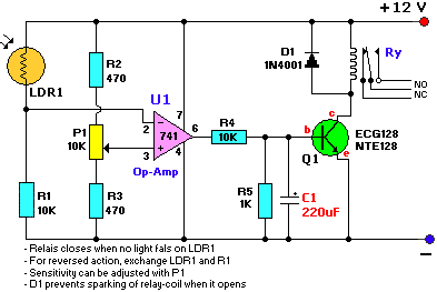
light dark sensor with relay circuit
The schematic diagram has been modified to include a 220µF smoothing capacitor connected between the base of transistor Q1 and ground. This addition effectively mitigated the issue of relay chatter, which involved rapid on/off switching at light levels. The incorporation...
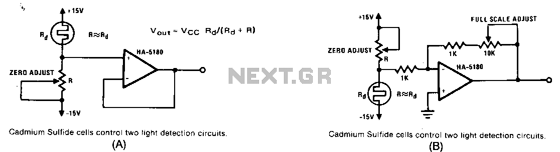
Light-level-detector
If R, the sensor matching resistor, is equal to the "dark" resistance of the cadmium sulfide cell, the amplifier output will range from 0 to 2 as the light level varies from "dark" to "bright." The circuit operates similarly, but...