


A circuit diagram of a switching power supply
#switching power supply
#voltage instability
#12V
#output section
#secondary winding
#power supply circuit
#voltage regulation
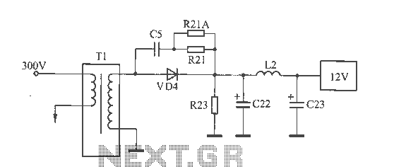
Description: The 12V voltage instability should first be investigated by checking the output section of the switching power supply, as illustrated in the accompanying figure. The secondary winding of the transformer and the switch VD4 have been examined and found to be normal, with no evidence of welding in inductor L2. The filter capacitors C22 and C23 are rated at 1000pF / 16V. Measurements taken with a capacitance meter indicate that C23 is functioning normally, although its capacitance has slightly decreased. In contrast, the capacitance of C22 has fallen to less than 80µF. The analysis of C22 and C23 reveals that the main power supply is mounted within the base of the monitor, where space is limited and heat dissipation is poor. C22 and C23 are located near the 12V rectifier diode, particularly C22, which is situated closer to it. The decreased capacitance of these capacitors, due to thermal stress, has resulted in the deterioration of the 12V output under load conditions. Despite this instability in the 12V output, the derived 5V and 3.3V supplies remain stable, as they do not fall below the converter limits, thus masking the underlying fault.
The schematic for the switching power supply includes a transformer with a secondary winding, which is responsible for stepping down the voltage. The output from this winding feeds into the rectifier circuit, which consists of diodes, including VD4, that convert the AC voltage to DC. The filter capacitors, C22 and C23, are critical components that smooth out the rectified output, ensuring a stable DC voltage. The design of the power supply must account for thermal management due to the compact layout within the monitor's base. The proximity of the capacitors to the rectifier diode leads to increased thermal stress, which can accelerate the aging process of the capacitors.
In this scenario, the failure of C22, due to its significant drop in capacitance, has a direct impact on the stability of the 12V output. The power supply's ability to maintain stable voltages for the 5V and 3.3V outputs is a result of their respective regulation circuits, which may compensate for fluctuations in the input voltage. However, the underlying issue with the 12V output remains a concern, as it can lead to potential operational failures in devices relying on this voltage level. Regular maintenance and monitoring of the power supply components, especially in heat-sensitive environments, are essential for ensuring long-term reliability and performance.12V voltage instability, you should first check the switching power supply output section, as shown in FIG. The secondary winding of the transformer and the switch VD4 examination were normal, no inductor L2 Weld phenomenon. Filter capacitors C22 and C23 parameters are 1000pF / 16V, measuring capacitance meter C23, normal (capacity decreased slightly), but the C22 capacity has dropped to less than 80 F, the C22, C23 with the analysis of the reasons is the machine's main power mounted within the base of the monitor, the space is small, poor heat dissipation, and C22, C23 are close to 12V rectifier diode (especially C22 closer together), decreased capacity after being baked to make 12V with a load capacity deteriorates, and then this failure. Although derived from the 5V and 3.3V 12V, 12V instability but not down to 5V and 3.3V supply voltage converter limit or less, so the two voltages have been normal, and thus conceal the nature of the fault.
The schematic for the switching power supply includes a transformer with a secondary winding, which is responsible for stepping down the voltage. The output from this winding feeds into the rectifier circuit, which consists of diodes, including VD4, that convert the AC voltage to DC. The filter capacitors, C22 and C23, are critical components that smooth out the rectified output, ensuring a stable DC voltage. The design of the power supply must account for thermal management due to the compact layout within the monitor's base. The proximity of the capacitors to the rectifier diode leads to increased thermal stress, which can accelerate the aging process of the capacitors.
In this scenario, the failure of C22, due to its significant drop in capacitance, has a direct impact on the stability of the 12V output. The power supply's ability to maintain stable voltages for the 5V and 3.3V outputs is a result of their respective regulation circuits, which may compensate for fluctuations in the input voltage. However, the underlying issue with the 12V output remains a concern, as it can lead to potential operational failures in devices relying on this voltage level. Regular maintenance and monitoring of the power supply components, especially in heat-sensitive environments, are essential for ensuring long-term reliability and performance.12V voltage instability, you should first check the switching power supply output section, as shown in FIG. The secondary winding of the transformer and the switch VD4 examination were normal, no inductor L2 Weld phenomenon. Filter capacitors C22 and C23 parameters are 1000pF / 16V, measuring capacitance meter C23, normal (capacity decreased slightly), but the C22 capacity has dropped to less than 80 F, the C22, C23 with the analysis of the reasons is the machine's main power mounted within the base of the monitor, the space is small, poor heat dissipation, and C22, C23 are close to 12V rectifier diode (especially C22 closer together), decreased capacity after being baked to make 12V with a load capacity deteriorates, and then this failure. Although derived from the 5V and 3.3V 12V, 12V instability but not down to 5V and 3.3V supply voltage converter limit or less, so the two voltages have been normal, and thus conceal the nature of the fault.
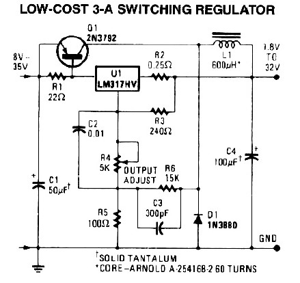
3A Switching Power Supply
The following diagram illustrates a 50W offline switching power supply circuit design. The circuit is powered by a MOSFET, specifically the BUZ80A/IXTP4N8 for a 220V AC voltage input and the GE IRF823 for a 110V AC input voltage. The output...
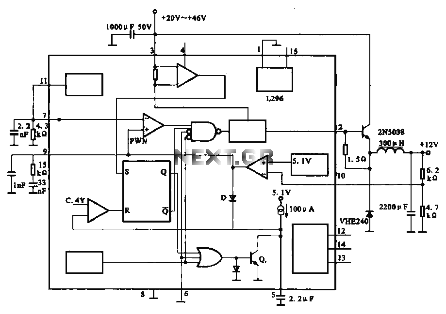
Output 12V-10A power circuit
The circuit outputs 12V at 10A and utilizes a high-current switching power supply design based on the L296 component. This configuration allows for an output current of up to 10A, and the entire circuit is compact with minimal component usage.
The...
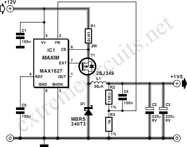
12V Glow Plug Converter
Most small internal combustion engines commonly used in model building utilize glow plugs for starting. However, glow plugs operate at a voltage of 1.5 V, while components such as fuel pumps, starter motors, and chargers typically operate at 12 V....
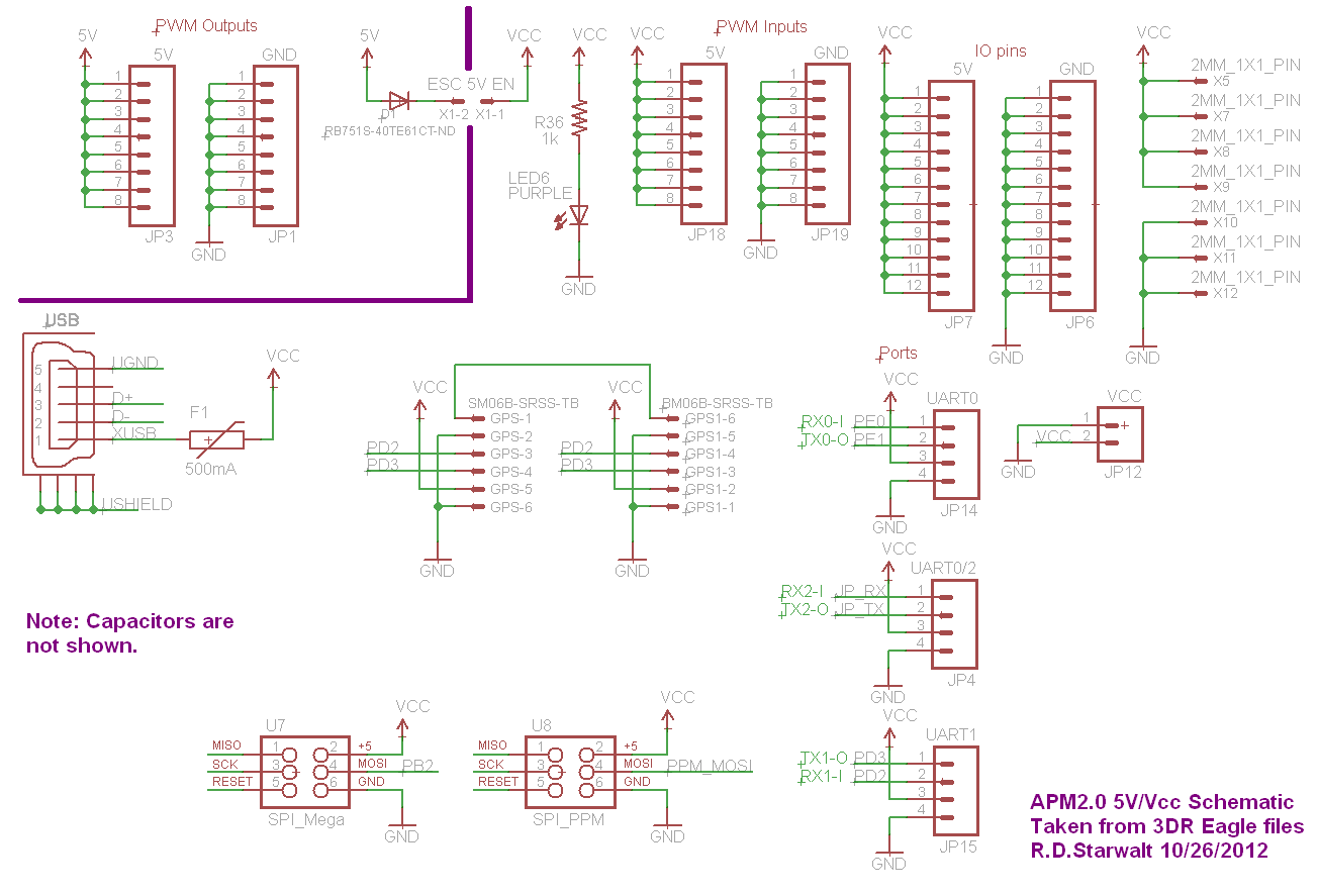
APM2.0 5V/Vcc Schematic
The PWM Output section has been separated into the upper left corner, delineated by a heavy purple line that is bridged by jumper JP1 on the APM2.0. This design choice highlights that diode D1 allows current to pass through JP1,...
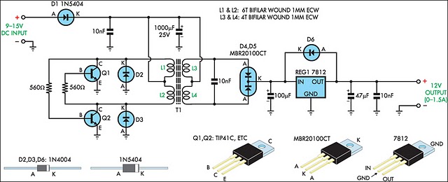
12v regulated inverter supply
When operating 12V electronic devices from lead-acid battery banks, the voltage supplied to the appliance can fluctuate significantly, ranging from below 11V when the batteries are discharged to over 14V during the charging process. Many appliances are not capable of...

12 Volt Toilet Tank Refiller
A flushing toilet is often taken for granted by city dwellers, but it can be a luxury for those living off the grid without access to utility water and electricity. This circuit enables on-off pump switching for a small 12...
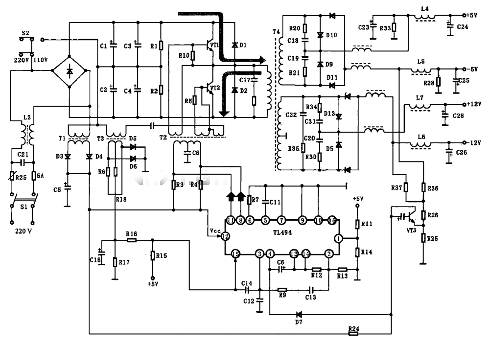
BE-150 mainframe computer switching power supply circuit
The BE-150 mainframe computer features a switching power supply circuit. The circuit utilizes the oscillation control IC TIA94. A 22V voltage is supplied through the power switch S1, fuse, filter capacitor C21, L2, and a mutual inductance filter, which rectifies...
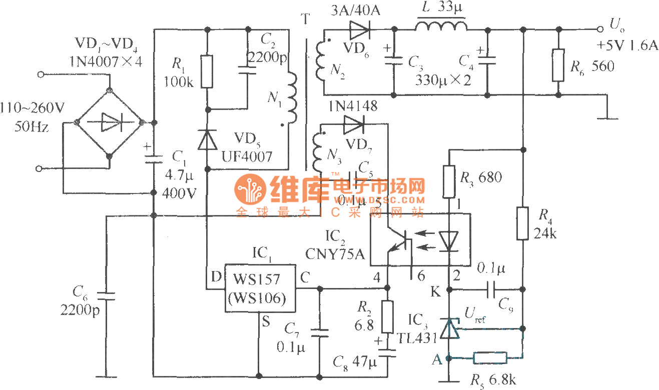
+5V 1.6A precision switching power supply circuit
The +5V, 1.6A precision switching power supply circuit is depicted in the figure. This circuit utilizes a photoelectric coupler (CNY75A) and an adjustable precision parallel regulator (TIA31). R3 serves as the current limiting resistor, while R4 and R5 function as...
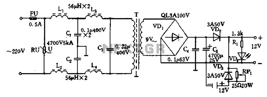
12V DC power supply circuit
12V DC power supply circuit. A typical 12V DC power supply circuit includes a transformer that converts mains voltage to the required 12V AC output. It features a full-wave rectifier and a capacitor filter. The circuit typically incorporates a series...