


Ac-solid-state-relays
#solid-state relay
#analog signals
#Schmitt-trigger
#transistor
#constant-current source
#IRED
#hysteresis
#power output
#biasing
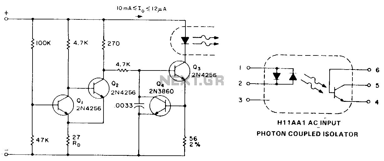
Description: When analog signals serve as the logic control, hysteresis from a Schmitt-trigger input can be utilized to prevent high-wave power output. The circuit functions as follows: at low input voltages, Q1 is biased in the off state. Q2 conducts and biases Q3, causing the IRED to turn off. Once the base of Q1 reaches the biasing voltage of 0.6 V, in addition to the drop across Rv, Q1 turns on. This provides base drive to Q3, activating the solid-state relay input. The combination of Q3 and Q4 operates as a constant current source for the IRED. To turn off Q3, the base drive must be reduced to pull it out of saturation. As Q2 remains in the off state when the signal decreases, Q1 will continue to stay on due to a base bias voltage lowered by the change in the drop across RD. With these parameters, the maximum turn-off voltage is 1.0 V, while the turn-on voltage is below the 4.1 V supplied to the circuit. For AC or bipolar input signals, various connections are possible. If only positive signals are used to activate the relay, a diode, such as the A14, can be connected in parallel to protect the IRED from reverse voltage damage, as its specified peak reverse voltage capability is approximately 3 V. If AC signals are employed, or if activation needs to be polarity insensitive, a H11AA coupler, which contains two LEDs in an antiparallel configuration, can be used. For high-input voltage designs or for an easy means of converting a DC input relay to AC, a full-wave diode bridge can be utilized to bias the IRED.
This circuit employs a Schmitt-trigger configuration to enhance the reliability of analog signal processing, particularly in controlling a solid-state relay (SSR) through a light-emitting diode (IRED). The hysteresis characteristic of the Schmitt trigger ensures that the switching thresholds for turning the output on and off are distinct, thereby preventing unwanted oscillations when the input signal hovers around the threshold voltage.
In the described operation, Q1 acts as a critical control transistor, which remains off until the input voltage exceeds 0.6 V, factoring in the voltage drop across resistor Rv. The activation of Q1 allows Q3 to receive base drive, thus enabling the SSR to conduct. Q2’s role is pivotal as it provides the necessary biasing to Q3 when the input is low, ensuring that the IRED remains off and preventing any false triggering of the relay.
The circuit's design allows for flexibility with input signals. When using only positive signals, the incorporation of a protective diode (A14) is essential to safeguard the IRED from potential reverse voltage, which could exceed its maximum rating. This diode ensures that any negative transients do not damage the LED.
For applications requiring AC signals or those that need to be insensitive to polarity, the H11AA optocoupler is an effective choice. Its dual LED configuration allows for bidirectional signal transfer, maintaining functionality regardless of the input signal's polarity.
In scenarios demanding high input voltage tolerance or where a straightforward conversion from DC to AC is necessary, a full-wave diode bridge can be integrated into the design. This component rectifies the input AC voltage, providing a stable DC bias to the IRED, thus enhancing the circuit's versatility and reliability in various applications.
Overall, this circuit design exemplifies a robust approach to controlling an SSR using analog signals, ensuring stable operation across a range of input conditions while protecting sensitive components from voltage spikes.In the case where analog signals are being used as the logic control, hysteresis from a Schmitt-trigger input can be used to prevent haH-wave power output. The circuit operation is as follows: at low input voltages, Q1 is biased in the off state. Q2 conducts and biases Q3, and the IRED turns off. When the base of Q1 reaches the biasing voltage of 0.6 V, plus the drop across Rv. Q1 turns on. Q3 is then supplied base drive, and the solid-state relay input will be activated. The combination of Q3 and Q4 acts as a constantcurrent source to the IRED. In order to tum-off Q3, the base drive must be reduced to pull it out of saturation. Because Q2 is in the off-state as the signal is reduced, Q1 will now stay on to a base bias-voltage lowered by the change in the drop across RD· With these values, the highest tum-off voltage is 1.0 V, while tum-on will be at less than the 4.1 V supplied to the circuit. For ac or bipolar input signals, there are several possible connections. Ifonly positive signals are set to activate the relay, a diode, such as the A14, can be connected in parallel to protect the IRED from reverse voltage damage, since its specified peak reverse voltage capability is approximately 3 V.
Ifac signals are being used, or if activation is to be polarity insensitive, a HllAA coupler, which contains two LEDs in antiparallel connection, can be used. For high-input voltage designs, or for any easy means of converting a de input relay to ac, a full-wave diode bridge can be used to bias the IRED.
This circuit employs a Schmitt-trigger configuration to enhance the reliability of analog signal processing, particularly in controlling a solid-state relay (SSR) through a light-emitting diode (IRED). The hysteresis characteristic of the Schmitt trigger ensures that the switching thresholds for turning the output on and off are distinct, thereby preventing unwanted oscillations when the input signal hovers around the threshold voltage.
In the described operation, Q1 acts as a critical control transistor, which remains off until the input voltage exceeds 0.6 V, factoring in the voltage drop across resistor Rv. The activation of Q1 allows Q3 to receive base drive, thus enabling the SSR to conduct. Q2’s role is pivotal as it provides the necessary biasing to Q3 when the input is low, ensuring that the IRED remains off and preventing any false triggering of the relay.
The circuit's design allows for flexibility with input signals. When using only positive signals, the incorporation of a protective diode (A14) is essential to safeguard the IRED from potential reverse voltage, which could exceed its maximum rating. This diode ensures that any negative transients do not damage the LED.
For applications requiring AC signals or those that need to be insensitive to polarity, the H11AA optocoupler is an effective choice. Its dual LED configuration allows for bidirectional signal transfer, maintaining functionality regardless of the input signal's polarity.
In scenarios demanding high input voltage tolerance or where a straightforward conversion from DC to AC is necessary, a full-wave diode bridge can be integrated into the design. This component rectifies the input AC voltage, providing a stable DC bias to the IRED, thus enhancing the circuit's versatility and reliability in various applications.
Overall, this circuit design exemplifies a robust approach to controlling an SSR using analog signals, ensuring stable operation across a range of input conditions while protecting sensitive components from voltage spikes.In the case where analog signals are being used as the logic control, hysteresis from a Schmitt-trigger input can be used to prevent haH-wave power output. The circuit operation is as follows: at low input voltages, Q1 is biased in the off state. Q2 conducts and biases Q3, and the IRED turns off. When the base of Q1 reaches the biasing voltage of 0.6 V, plus the drop across Rv. Q1 turns on. Q3 is then supplied base drive, and the solid-state relay input will be activated. The combination of Q3 and Q4 acts as a constantcurrent source to the IRED. In order to tum-off Q3, the base drive must be reduced to pull it out of saturation. Because Q2 is in the off-state as the signal is reduced, Q1 will now stay on to a base bias-voltage lowered by the change in the drop across RD· With these values, the highest tum-off voltage is 1.0 V, while tum-on will be at less than the 4.1 V supplied to the circuit. For ac or bipolar input signals, there are several possible connections. Ifonly positive signals are set to activate the relay, a diode, such as the A14, can be connected in parallel to protect the IRED from reverse voltage damage, since its specified peak reverse voltage capability is approximately 3 V.
Ifac signals are being used, or if activation is to be polarity insensitive, a HllAA coupler, which contains two LEDs in antiparallel connection, can be used. For high-input voltage designs, or for any easy means of converting a de input relay to ac, a full-wave diode bridge can be used to bias the IRED.

Economical Transistor Radio
The schematic diagram illustrates an audio stage utilizing a common-collector circuit. This configuration does not dampen the tuned circuit; rather, it enhances its response, resulting in improved sensitivity and selectivity. Due to the low supply voltage, the subsequent audio amplifier...
One Transistor Pump Building Block
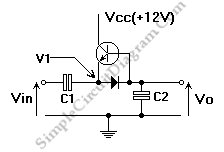
This is a single transistor pump circuit. It is a straightforward circuit that is quite useful and can serve as a foundational component for designing more complex electronic systems.
The single transistor pump circuit utilizes a transistor as the primary active...
A lamp flasher circuit using transistors
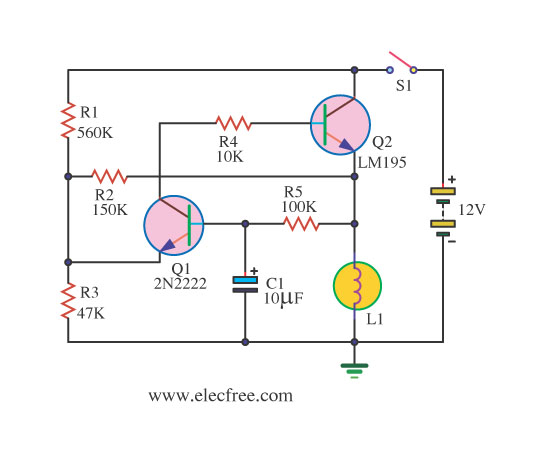
If you require a small lamp that flashes for general use, there are numerous options available. Today, three lamp flasher circuits will be presented.
The three lamp flasher circuits can be designed using different components and configurations, each offering unique characteristics...
transistors How does this circuit diagram work
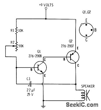
R2 controls the charging speed of capacitor C1. At a specific charge level, C1 triggers transistors Q1 and Q2, which release a 9-volt pulse. This pulse generates a clicking sound. The discharge process of the capacitor involves it charging gradually...
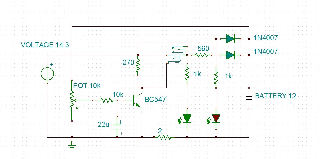
modified battery charger circuit
Using a transistor will not yield accurate results, and the adjustment process can become quite tedious. The circuit is technically correct; if the tripping point can be adjusted properly, it may function as intended. Vinod states that he created a...
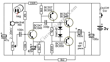
Small Amplifier Using Transistors
The output of this circuit is push-pull and consumes less than 3 mA (with no signal) but drives the earpiece to a very loud level when audio is detected.
This circuit operates in a push-pull configuration, which allows it to efficiently...
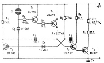
Simple Electronic bell circuit using transistors
A simple and practical electronic bell circuit can be constructed using the provided schematic diagram. This circuit can function as a doorbell or an alarm system. It utilizes only a few transistors along with several common components. The circuit is...

metal detector circuit
This circuit diagram represents a low-cost metal detector utilizing a single transistor circuit in conjunction with an old pocket radio. It operates as a Colpitts oscillator functioning within the medium band frequency range, with the radio tuned to the same...
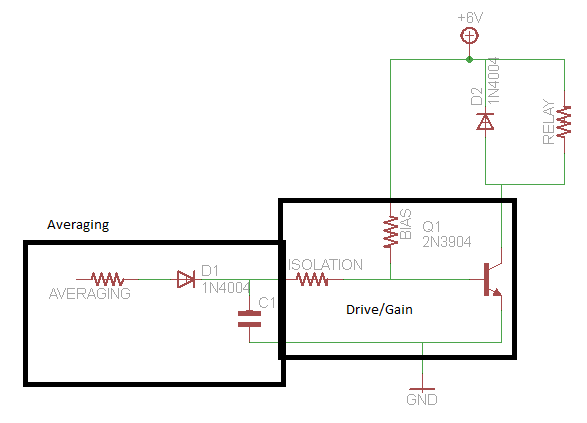
transistors audio controlled relay circuit
A circuit that activates a relay upon detecting audio pulses from one channel of an MP3 player. The intention is to synchronize recorded audio pulses with music to control a motor for mouth movement. For a stereo player, music or...