


Breaker control signal circuit of the electromagnetic actuator
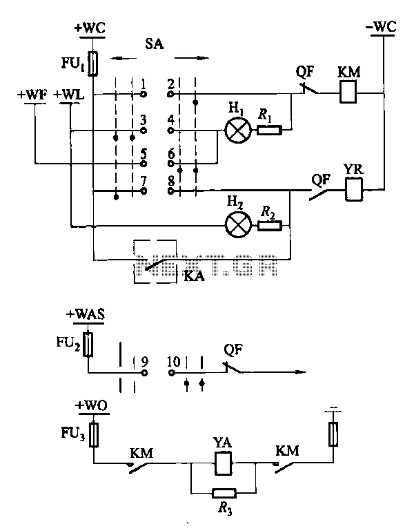
Description: Factories and enterprises operating at voltages of 10 kV and below commonly utilize the CD10 (formerly CD2) type electromagnetic actuator as a circuit breaker. This mechanism features a mechanical anti-jump device. The control signal circuit for the CD10 actuator is illustrated in Figure 6-70. In this figure, wc represents the control for a small bus; WL indicates a light for the small bus; WF denotes a small flash signal bus; WAS corresponds to the accident sound for the small bus; w0 signifies the closing gate for the small bus; SA controls the switch; KM is the circuit breaker QF closing contacts device; YR is the trip coil; YA is the electromagnetic closing coil; KA is for the export of relay contacts; Hi represents the green indicator light; H2 is the red LED; and R3 serves as a discharge resistor.
The CD10 electromagnetic actuator is integral to the operation of circuit breakers in low-voltage applications, particularly in industrial settings. The actuator's design incorporates a mechanical anti-jump device, ensuring reliable operation and enhanced safety. The control signal circuit, as depicted in Figure 6-70, outlines the various connections and functionalities essential for effective circuit management.
The circuit includes multiple components that facilitate the operation of the actuator. The small bus control (wc) is crucial for managing the flow of signals to the actuator, while the light indicator (WL) provides visual feedback regarding the status of the small bus. The flash signal bus (WF) is used for alerting operators of specific conditions, and the accident sound bus (WAS) serves as an auditory warning system in case of faults or emergencies.
The closing gate control (w0) is responsible for the physical actuation involved in closing the circuit, while the switch control (SA) allows for manual intervention when necessary. The circuit breaker (KM) acts as a safety device, ensuring that the electrical circuit is interrupted in case of overloads or faults. The trip coil (YR) and electromagnetic closing coil (YA) are critical for the actuation mechanism, providing the necessary electromagnetic force to operate the breaker.
Relay contacts (KA) facilitate the communication between various components of the circuit, allowing for coordinated operation. The green indicator light (Hi) provides a visual cue that the system is functioning correctly, whereas the red LED (H2) indicates a fault or an operational issue. Finally, the discharge resistor (R3) is employed to safely dissipate any residual charge in the circuit, ensuring that the system remains safe for maintenance and operation.
Overall, the CD10 actuator and its associated control circuit play a vital role in the safe and efficient operation of low-voltage electrical systems in industrial environments.Factories and enterprises lOkV and below the circuit breaker commonly used CD10 (formerly CD2) type electromagnetic actuator. This type of mechanism itself has a mechanical ant i-jump device. Adopt breaker control signal circuit CD10 Actuator type shown in Figure 6-70. Figure, wc for the control of small bus; WL for a light indicating a small bus; WF is a small flash signal bus; WAS the accident sound small bus; w0 is closing the gate a small bus; SA controls switch; KM circuit breaker QF closing contacts device; YR to the trip coil; YA electric magnetic closing coil; KA for the export of relay contacts; Hi for the green indicator light; H2 red LED; R3 is a discharge resistor.
The CD10 electromagnetic actuator is integral to the operation of circuit breakers in low-voltage applications, particularly in industrial settings. The actuator's design incorporates a mechanical anti-jump device, ensuring reliable operation and enhanced safety. The control signal circuit, as depicted in Figure 6-70, outlines the various connections and functionalities essential for effective circuit management.
The circuit includes multiple components that facilitate the operation of the actuator. The small bus control (wc) is crucial for managing the flow of signals to the actuator, while the light indicator (WL) provides visual feedback regarding the status of the small bus. The flash signal bus (WF) is used for alerting operators of specific conditions, and the accident sound bus (WAS) serves as an auditory warning system in case of faults or emergencies.
The closing gate control (w0) is responsible for the physical actuation involved in closing the circuit, while the switch control (SA) allows for manual intervention when necessary. The circuit breaker (KM) acts as a safety device, ensuring that the electrical circuit is interrupted in case of overloads or faults. The trip coil (YR) and electromagnetic closing coil (YA) are critical for the actuation mechanism, providing the necessary electromagnetic force to operate the breaker.
Relay contacts (KA) facilitate the communication between various components of the circuit, allowing for coordinated operation. The green indicator light (Hi) provides a visual cue that the system is functioning correctly, whereas the red LED (H2) indicates a fault or an operational issue. Finally, the discharge resistor (R3) is employed to safely dissipate any residual charge in the circuit, ensuring that the system remains safe for maintenance and operation.
Overall, the CD10 actuator and its associated control circuit play a vital role in the safe and efficient operation of low-voltage electrical systems in industrial environments.Factories and enterprises lOkV and below the circuit breaker commonly used CD10 (formerly CD2) type electromagnetic actuator. This type of mechanism itself has a mechanical ant i-jump device. Adopt breaker control signal circuit CD10 Actuator type shown in Figure 6-70. Figure, wc for the control of small bus; WL for a light indicating a small bus; WF is a small flash signal bus; WAS the accident sound small bus; w0 is closing the gate a small bus; SA controls switch; KM circuit breaker QF closing contacts device; YR to the trip coil; YA electric magnetic closing coil; KA for the export of relay contacts; Hi for the green indicator light; H2 red LED; R3 is a discharge resistor.
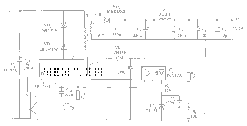
5V / 2A isolated switching power supply circuit diagram
The circuit diagram includes an input filter capacitor C1 and a primary clamp composed of VDz and VD1. The resistor R1 is connected to the control terminal. C2 serves as a bypass capacitor. The TOP414GC-S is connected in parallel to...
Burst-power-control
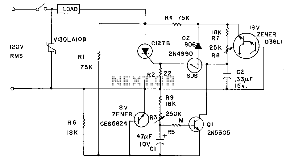
Industrial applications sometimes require that power be briefly applied to a load following the closure of a switch, such as a microswitch or foot switch. The load could be a heating element used for sealing plastic bags, a DC motor...

13.8V 40A Switching Power Supply By LM3524 and LM324 PCB
This article was originally published in a slightly modified form in the QST magazine, December 1998 and January 1999, and in the Radio Amateur's Handbook, 1999. Visit the American Radio Relay League for information on these publications and a world...
Switching Power Supply
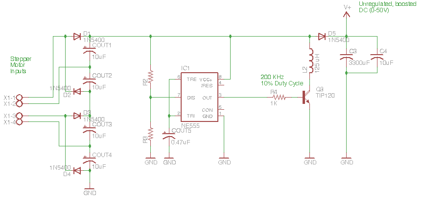
The circuit depicted in the schematic below represents an enhanced generator electronics system. It is an unregulated switcher designed to maximize sound output while ensuring prolonged CPU operation. This circuit efficiently transfers electrical energy from the generator, outperforming traditional rectifier...
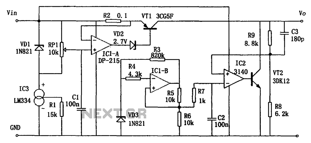
High-performance power supply LM334
The circuit functions as a switching power supply designed to operate alongside a linear regulated power supply. Key characteristics include high efficiency and low dropout voltage. It effectively filters out high-frequency ripple voltage and manages instantaneous voltage variations, making it...
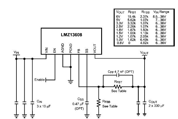
LMZ13608 8A switching power supply circuit design
A simple, high-efficiency switching power supply circuit can be designed using the LMZ13608 8A regulator. This regulator offers very high efficiency and requires few external components. It supports a wide input voltage range of 6 to 36 volts and provides...
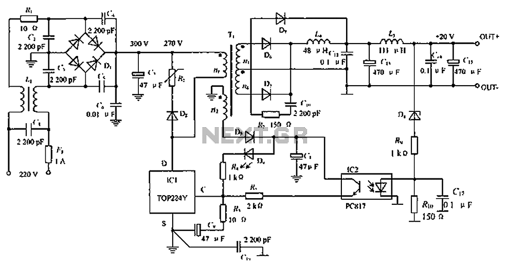
Low-noise switching power supply schematic circuit diagram
The circuit depicted in the figure is designed to achieve a higher power output by modifying specific components. On the left side of the figure, components R1, L1, D1, and capacitors C1 to C7 form a conventional filtering and rectifying...
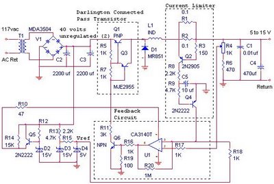
Schematics power supply switching PCB
The switching power supply provides 12 volts at a maximum of 10 amps, utilizing a discrete transistor regulator with an operational amplifier acting as a comparator in the feedback circuit. The schematic does not depict the front panel power-on indicator....
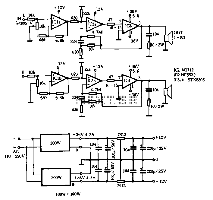
Switching power supply circuit with STK6303
The T amplifier circuit schematic section is illustrated in Figure 3-51. It utilizes the Japan Sanyo STK6303 Pina, which is a high-power thick film integrated circuit. The maximum power supply voltage is 36V, and the output current can reach approximately...