


clap switch circuit here is hobby
#clap switch
#microphone
#transistor
#sound activated
#hobby circuit
#switching
#amplifier
#home automation
#DIY electronics
#sensor
Description: This is a hobby circuit designed for electronics enthusiasts that can turn on and off devices such as lights, fans, and radios in response to the sound of a clap. The sound is detected by a small microphone, which is biased by resistor R1 in the circuit. The microphone converts sound waves into electrical signals, which are then amplified by transistor Q1. Q1 functions as a common emitter amplifier to boost the weak signals received from the microphone. The amplified output from the collector of Q1 is fed into a bistable multivibrator circuit, also referred to as a flip-flop circuit, constructed with two transistors, Q2 and Q3. In a flip-flop circuit, only one transistor conducts at any given time while the other is turned off. When triggered by an external pulse, the first transistor turns off, and the second transistor turns on. Consequently, the output of the flip-flop alternates between logic-0 and logic-1, maintaining its state until receiving another trigger pulse. The clap sound serves as the trigger for the flip-flop, causing the output to change states. However, the flip-flop output, which is in a low current form, cannot drive a relay directly; therefore, a current amplifier circuit using Q4, also configured as a common emitter, is employed. The output from Q4 is connected to a relay (an electromagnetic switch), which functions like a mechanical switch, facilitating the connection of other electrical appliances.
The circuit operates by first detecting the sound of a clap through the microphone, which is typically a small electret microphone. The microphone's output is an AC signal that is biased by R1 to ensure it is suitable for amplification. The transistor Q1 is configured in a common emitter arrangement, providing significant voltage gain to the weak microphone signal. This amplification is crucial, as it allows the subsequent flip-flop stage to operate reliably by ensuring that the signal level is sufficient to trigger the transistors Q2 and Q3.
The bistable multivibrator configuration is essential for creating a stable on/off output based on the input trigger. The two transistors are arranged such that when one is turned on, the other is turned off, creating a stable state. The output from the flip-flop can be connected to various devices, but since its current capacity is limited, it is necessary to amplify the output further. The common emitter configuration of Q4 serves this purpose, providing the necessary current to activate the relay.
The relay acts as a switch to control higher power devices, isolating the low-power logic circuit from the high-power load. When the relay is energized by the output of Q4, it closes its contacts, allowing current to flow to the connected device, such as a light or fan. This design is particularly useful for hobbyists looking to create interactive electronic projects that respond to sound, showcasing fundamental principles of electronics, including amplification, signal processing, and switching mechanisms. The circuit is not only educational but also practical, offering a hands-on approach to learning about electronic components and their applications.Here is a Hobby Circuit for electronics hobbyists that can switch on & off a light, Fan, Radio etc. by the sound of clap. The sound of clap is received by a small microphone that is shown biased by resistor R1 in the circuit. The microphone changes sound wave in to electrical wave which is further amplified by Q1. Transistor Q1 is used as common em itter circuit to amplify weak signals received by the microphone. Amplified output from the collector of transistor Q1 is then feed to the Bistable Multivibrator circuit also known as flip-flop circuit. Flip flop circuit is made by using 2 Transistor, in our circuit Q2&Q3. In a flip-flop circuit, at a time only one transistor conduct and other cut off and when it gets a trigger pulse from outside source then first transistor is cutoff and 2nd transistor conducts.
Thus output of transistor is either logic-0 or logic-1 and it remains in one state 0 or 1 until it gets trigger pulse from outer source. The pulse of clap which is a trigger for flip-flop which makes changes to the output which is complementary (reverse).
Output of flip-flop which is in the low current form is unable to drive relay directly so we have used a current amplifier circuit by using Q4 which is a common emitter circuit. Output of Q4 is connected to a Relay (Electromagnetic switch) which works like a mechanical switch and it becomes easy for connecting other electrical appliance.
The circuit operates by first detecting the sound of a clap through the microphone, which is typically a small electret microphone. The microphone's output is an AC signal that is biased by R1 to ensure it is suitable for amplification. The transistor Q1 is configured in a common emitter arrangement, providing significant voltage gain to the weak microphone signal. This amplification is crucial, as it allows the subsequent flip-flop stage to operate reliably by ensuring that the signal level is sufficient to trigger the transistors Q2 and Q3.
The bistable multivibrator configuration is essential for creating a stable on/off output based on the input trigger. The two transistors are arranged such that when one is turned on, the other is turned off, creating a stable state. The output from the flip-flop can be connected to various devices, but since its current capacity is limited, it is necessary to amplify the output further. The common emitter configuration of Q4 serves this purpose, providing the necessary current to activate the relay.
The relay acts as a switch to control higher power devices, isolating the low-power logic circuit from the high-power load. When the relay is energized by the output of Q4, it closes its contacts, allowing current to flow to the connected device, such as a light or fan. This design is particularly useful for hobbyists looking to create interactive electronic projects that respond to sound, showcasing fundamental principles of electronics, including amplification, signal processing, and switching mechanisms. The circuit is not only educational but also practical, offering a hands-on approach to learning about electronic components and their applications.Here is a Hobby Circuit for electronics hobbyists that can switch on & off a light, Fan, Radio etc. by the sound of clap. The sound of clap is received by a small microphone that is shown biased by resistor R1 in the circuit. The microphone changes sound wave in to electrical wave which is further amplified by Q1. Transistor Q1 is used as common em itter circuit to amplify weak signals received by the microphone. Amplified output from the collector of transistor Q1 is then feed to the Bistable Multivibrator circuit also known as flip-flop circuit. Flip flop circuit is made by using 2 Transistor, in our circuit Q2&Q3. In a flip-flop circuit, at a time only one transistor conduct and other cut off and when it gets a trigger pulse from outside source then first transistor is cutoff and 2nd transistor conducts.
Thus output of transistor is either logic-0 or logic-1 and it remains in one state 0 or 1 until it gets trigger pulse from outer source. The pulse of clap which is a trigger for flip-flop which makes changes to the output which is complementary (reverse).
Output of flip-flop which is in the low current form is unable to drive relay directly so we have used a current amplifier circuit by using Q4 which is a common emitter circuit. Output of Q4 is connected to a Relay (Electromagnetic switch) which works like a mechanical switch and it becomes easy for connecting other electrical appliance.
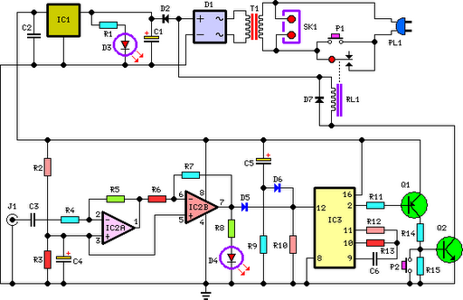
Amplifier Timer Circuit Schematic
This circuit deactivates an amplifier or any connected device when a low-level audio signal at its input is absent for at least 15 minutes. Pressing P1 turns the device on, supplying power to any appliance connected to SK1. The input...
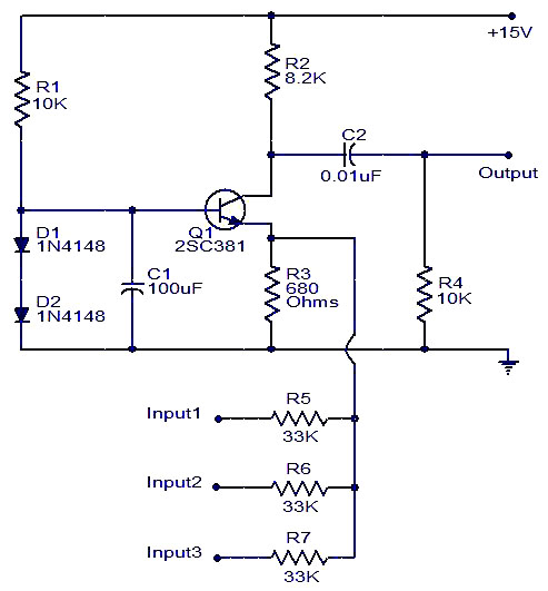
Single transistor audio mixer
Numerous audio mixer circuits have been published; however, this particular design is among the simplest. This straightforward audio mixer circuit utilizes only a single transistor. The base-emitter junction of the transistor is biased with diodes D1 and D2. The signals...

Transistor Ignition
This transistor ignition circuit enhances vehicle starting and ensures smoother engine operation, especially at both high and low RPMs. It contributes to lower fuel consumption, reduced emissions, and decreased maintenance costs. The system promotes economical and electronic driving.
The transistor ignition...
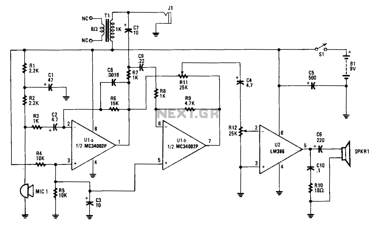
Hands-off-intercom
Amplifier A increases the microphone's output to a usable level. The output signal is fed to op amp B, which inverts the signal by 180 degrees. A balance-control potentiometer connects across the outputs of amplifiers A and B. If an...
Low Supply Rail Detection
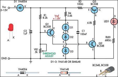
This is a simple low supply rail detection circuit that is inexpensive and can be assembled in approximately 20 minutes. Its low power consumption makes it suitable for integration into battery-powered devices. Instead of utilizing an operational amplifier, the circuit...

Sensor-Activated Relay Pulser Circuit
A sensor activates transistor Q1 to turn on the low-frequency 555 oscillator, which generates pulses to control LAMP II. The sensor may respond to variations in light or temperature. Either resistor RA or RB can function as the sensor, depending...
4 transistor 500mw fm transmitter
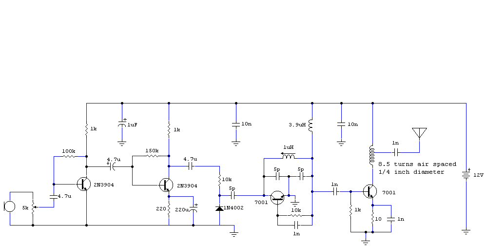
The audio circuit described is a microphone utilizing two 2N3904 transistors as the audio preamplifier. The audio/microphone gain is adjustable via a 5k preset potentiometer. The circuit employs a Colpitts oscillator for frequency generation, which is free-running and operates at...

Transistor circuit of a pressure gauge
To ensure proper operation of the transistor in a circuit, it is essential to measure the reverse breakdown voltage of the transistor. This is particularly important for tubes with high reverse breakdown voltage requirements, such as those used in OCL...

Current negative feedback voltage divider biasing circuit diagram
Current negative feedback voltage divider biased circuit diagram.
The current negative feedback voltage divider biased circuit is a configuration commonly used in electronic amplifiers to stabilize the operating point and improve linearity. This circuit typically consists of an amplifier, a voltage...