


High voltage speed optocoupler and application circuit diagram
#optocoupler
#high voltage
#isolation
#pulse transformer
#voltage stability
#switching circuit
#rise time
#transfer ratio
#breakdown voltage
#control system
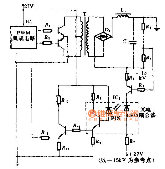
Description: The technical parameters of high-speed optocouplers include a rise time (t1) of less than or equal to 300 ns, a circuit transfer ratio (CTR) of 50%, an isolation voltage (VSO) of at least 15,000 V, and an output transistor reverse breakdown voltage (V(BR)CEO) of at least 50 V. These optical couplers are commonly utilized in high-voltage isolators, high-voltage pulse transformers, and high-voltage power circuit voltage stability control systems. The control systems are employed in high-voltage regulator circuits. The fast high-voltage electrical coupling in this circuit serves two primary functions: it facilitates the output voltage feedback loop in the input circuit while ensuring high-voltage isolation between low-voltage circuits, and it provides a high output voltage feedback signal. It is important to note that the high-pressure side requires a +27 V DC power supply, which must be independent and have a voltage level exceeding 15 kV.
High-speed optocouplers are essential components in modern electronic systems, especially in applications requiring efficient isolation and signal transfer across different voltage domains. The rise time of less than or equal to 300 ns indicates the rapid response of these devices, making them suitable for high-frequency applications. The circuit transfer ratio of 50% signifies that the output signal strength is half of the input signal strength, which is adequate for many control and feedback applications.
The isolation voltage rating of at least 15,000 V ensures that the optocoupler can safely operate in high-voltage environments without risk of breakdown or signal interference between the high-voltage and low-voltage sides. The reverse breakdown voltage of at least 50 V for the output transistor further enhances the reliability of the optocoupler in circuits where transient voltages may occur.
In high-voltage regulator circuits, these optocouplers play a critical role by providing feedback from the output to the input circuit, allowing for precise regulation of voltage levels while maintaining electrical isolation. This isolation is crucial for protecting sensitive low-voltage components from high-voltage spikes or noise, thereby ensuring the integrity and stability of the entire system.
The requirement for a +27 V DC power supply on the high-pressure side, which must exceed 15 kV, indicates the need for careful design considerations in power management and safety measures. This independent power supply arrangement helps maintain the necessary voltage levels for proper operation while minimizing the risk of interference or damage to the low-voltage side of the circuit.
Overall, high-speed optocouplers are indispensable in applications where high-voltage isolation, rapid signal transfer, and reliable feedback mechanisms are necessary for the effective operation of electronic systems.High speed optocouplers technical parameters are: Rise time t1 ‰¤ 300ns; Circuit eye transfer ratio CTR = 50%; Isolation voltage VSO ‰¥ 15000V; Output transistor reverse breakdown voltage V (BR) CEO ‰¥ 50V. The optical coupler can be widely used for the high-voltage isolators, high-voltage pulse transformers and high-voltage power circuit voltage stability control system.
T he control systems is used for high voltage regulator circuit. The fast high-voltage electrical coupling in this circuit play two roles. First one is to achieve the output voltage feedback loop in the input circuit and high voltage isolation between the low-voltage circuits; The other role is to achieve high output voltage feedback signal. Note: The high pressure side +27 V DC power supply is independent, but its pressure level must be greater than 15KV.
High-speed optocouplers are essential components in modern electronic systems, especially in applications requiring efficient isolation and signal transfer across different voltage domains. The rise time of less than or equal to 300 ns indicates the rapid response of these devices, making them suitable for high-frequency applications. The circuit transfer ratio of 50% signifies that the output signal strength is half of the input signal strength, which is adequate for many control and feedback applications.
The isolation voltage rating of at least 15,000 V ensures that the optocoupler can safely operate in high-voltage environments without risk of breakdown or signal interference between the high-voltage and low-voltage sides. The reverse breakdown voltage of at least 50 V for the output transistor further enhances the reliability of the optocoupler in circuits where transient voltages may occur.
In high-voltage regulator circuits, these optocouplers play a critical role by providing feedback from the output to the input circuit, allowing for precise regulation of voltage levels while maintaining electrical isolation. This isolation is crucial for protecting sensitive low-voltage components from high-voltage spikes or noise, thereby ensuring the integrity and stability of the entire system.
The requirement for a +27 V DC power supply on the high-pressure side, which must exceed 15 kV, indicates the need for careful design considerations in power management and safety measures. This independent power supply arrangement helps maintain the necessary voltage levels for proper operation while minimizing the risk of interference or damage to the low-voltage side of the circuit.
Overall, high-speed optocouplers are indispensable in applications where high-voltage isolation, rapid signal transfer, and reliable feedback mechanisms are necessary for the effective operation of electronic systems.High speed optocouplers technical parameters are: Rise time t1 ‰¤ 300ns; Circuit eye transfer ratio CTR = 50%; Isolation voltage VSO ‰¥ 15000V; Output transistor reverse breakdown voltage V (BR) CEO ‰¥ 50V. The optical coupler can be widely used for the high-voltage isolators, high-voltage pulse transformers and high-voltage power circuit voltage stability control system.
T he control systems is used for high voltage regulator circuit. The fast high-voltage electrical coupling in this circuit play two roles. First one is to achieve the output voltage feedback loop in the input circuit and high voltage isolation between the low-voltage circuits; The other role is to achieve high output voltage feedback signal. Note: The high pressure side +27 V DC power supply is independent, but its pressure level must be greater than 15KV.
0 1000 volt regulated high voltage
The input voltage for the high-voltage DC-DC converter is 12V AC at 800mA, which is then converted to DC using a 1A bridge rectifier diode. The output voltage of the converter can be adjusted within the range of 0-1000V DC....
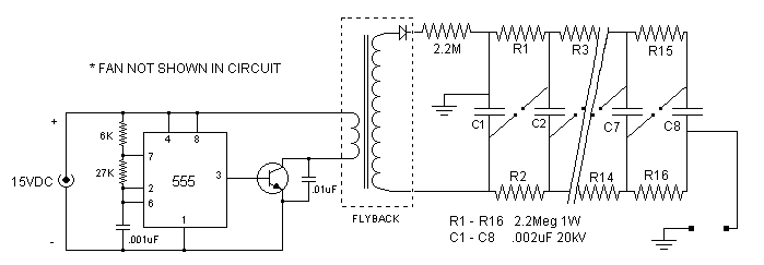
marx generator
The spark gap in the initial design consisted of copper wires bent into a ring at the end to suppress corona discharge. The current design is more advanced, utilizing spherical electrodes. This setup generates a 300 kV output pulse with...
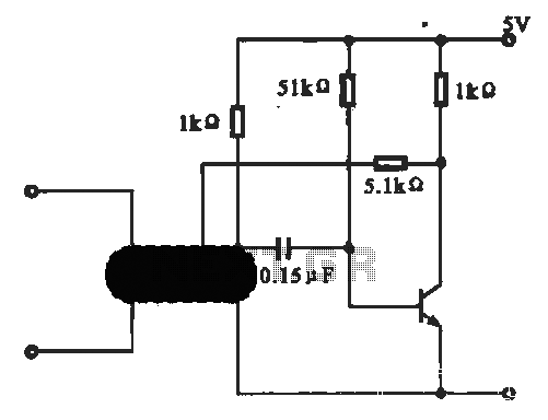
Oscillation circuit optocoupler control
This circuit illustrates an oscillator that is controlled by an optocoupler, utilizing photoelectric coupling to drive a transistor.
The oscillator circuit described operates by employing an optocoupler to provide electrical isolation between its input and output stages while allowing control signals...
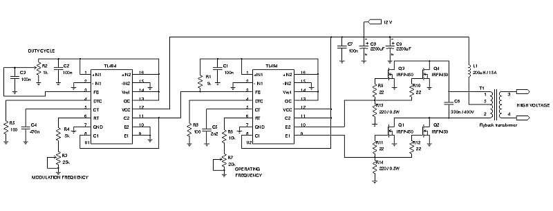
Portable Jacobs Ladder
Portable Jacob's Ladder circuit designed specifically for experimental purposes.
The Portable Jacob's Ladder circuit is an intriguing project that demonstrates the principles of high-voltage arc generation. This circuit is typically utilized in educational settings or experimental demonstrations, showcasing the behavior of...
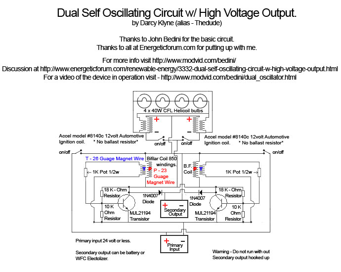
Bedini Self Oscillator High Voltage Output
A Tesla pancake coil is connected in series with a bifilar wound coil to generate resonance and a sharp gradient discharge, which creates a vacuum flux. The circuit operates with a CFL at approximately 0.07 amps and 12.42 volts, consuming...
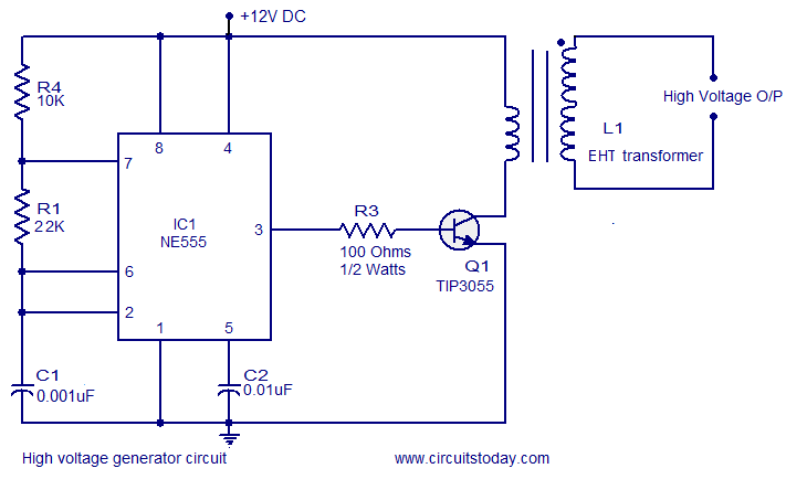
High voltage generator circuit
This circuit is highly dangerous due to its output voltage, which is in kilovolts and poses a significant risk of serious injury or death. It should only be attempted by individuals with extensive experience in handling high voltages. No responsibility...
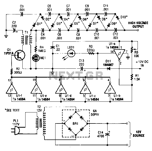
High-voltage-dc-generator
This circuit is powered by a 12-V DC power supply. The input to the circuit is amplified to generate a 10,000-V DC output. The output of the up-converter is subsequently directed into a 10-stage high-voltage multiplier to achieve a final...
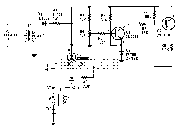
Capacitor-discharge-high-voltage-generator
A step-down transformer T1 reduces the incoming line voltage to approximately 48 Vac, which is then rectified by diode D1. The resulting direct current charges capacitor C1 through a current-limiting resistor R1 to a voltage level set by R4. When...
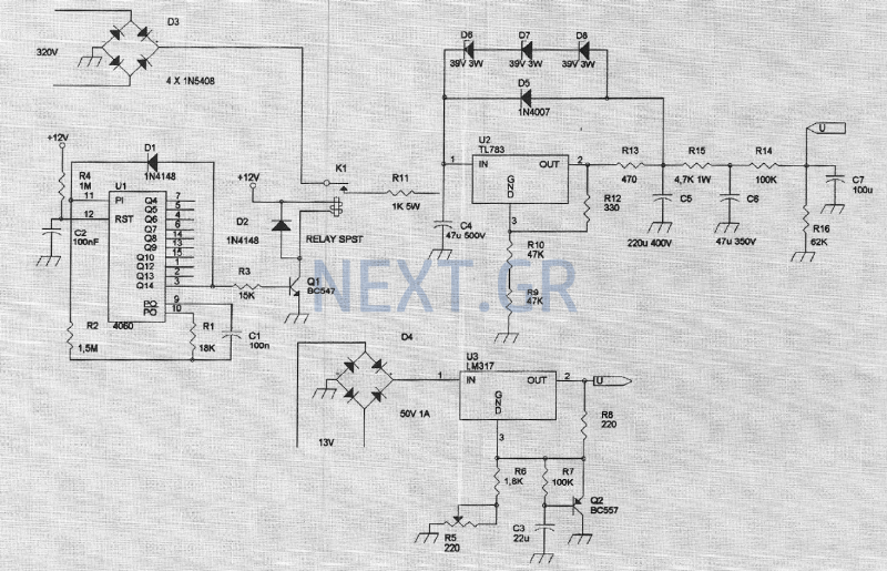
High Voltage Power Supply for Valve Preamplifiers
The amplifier feeding the final amplification stage operates with unstabilized voltage. The output stage, utilizing push-pull operation, exhibits significant rejection of the supply voltage. However, the earlier stages do not provide the same level of rejection, resulting in unwanted noise....