


opto isolator Optotriac+triac: how do I calculate the gate resistor
#opto isolator
#triac
#MOC3023
#BT136
#gate resistor
#AC switching
#heater control
#230VAC
#12VAC
#power resistor
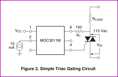
Description: A small circuit is being constructed to control a 200W heater using a MOC3023 optoisolator and a BT136 triac. The datasheet for the optotriac suggests a specific circuit configuration. The inquiry pertains to the determination of the 180-ohm resistor value, noting that it conducts for a brief period. Clarification is sought regarding the validity of this resistor value for both 230VAC and 12VAC applications, as well as the suitability of a 1/4W resistor.
The circuit involves using the MOC3023 optoisolator to drive the BT136 triac, which is responsible for switching the 200W heater on and off. The MOC3023 is designed to provide electrical isolation between the control circuit and the high voltage heater circuit, ensuring safety and reliability. The BT136 triac is capable of handling the power requirements of the heater, making it suitable for this application.
In determining the value of the 180-ohm resistor, several factors must be considered, including the forward current of the optoisolator's LED and the gate triggering current of the BT136. The resistor value is calculated using Ohm's law, taking into account the supply voltage and the desired current through the LED. The brief conduction time of the optoisolator is adequate for triggering the triac, as it allows for the necessary gate current to flow, enabling the BT136 to latch and control the heater.
Regarding the suitability of the 180-ohm resistor for both 230VAC and 12VAC, it is essential to analyze the circuit's operation under different voltage levels. The resistor should be capable of handling the power dissipation without exceeding its rated wattage. A 1/4W resistor may be appropriate if the calculated power dissipation remains below this threshold. However, it is advisable to verify the resistor's power rating based on the actual circuit conditions to ensure reliable operation.
In summary, the circuit effectively utilizes the MOC3023 and BT136 to control a 200W heater, with careful consideration given to the resistor value and power ratings to ensure safe and efficient operation across different voltage levels.Building a small circuit to turn on/off a 200W heater. I am using a MOC3023 and a BT136. At the datasheet of the the optotriac, this circuit is recommended: My question is how is the 180Ohm resistor value determined. I understand that it conducts for a very short time, but not much more. Is this a valid value for both 230VAC and 12VAC Is 1/4W resistor always fuitable
The circuit involves using the MOC3023 optoisolator to drive the BT136 triac, which is responsible for switching the 200W heater on and off. The MOC3023 is designed to provide electrical isolation between the control circuit and the high voltage heater circuit, ensuring safety and reliability. The BT136 triac is capable of handling the power requirements of the heater, making it suitable for this application.
In determining the value of the 180-ohm resistor, several factors must be considered, including the forward current of the optoisolator's LED and the gate triggering current of the BT136. The resistor value is calculated using Ohm's law, taking into account the supply voltage and the desired current through the LED. The brief conduction time of the optoisolator is adequate for triggering the triac, as it allows for the necessary gate current to flow, enabling the BT136 to latch and control the heater.
Regarding the suitability of the 180-ohm resistor for both 230VAC and 12VAC, it is essential to analyze the circuit's operation under different voltage levels. The resistor should be capable of handling the power dissipation without exceeding its rated wattage. A 1/4W resistor may be appropriate if the calculated power dissipation remains below this threshold. However, it is advisable to verify the resistor's power rating based on the actual circuit conditions to ensure reliable operation.
In summary, the circuit effectively utilizes the MOC3023 and BT136 to control a 200W heater, with careful consideration given to the resistor value and power ratings to ensure safe and efficient operation across different voltage levels.Building a small circuit to turn on/off a 200W heater. I am using a MOC3023 and a BT136. At the datasheet of the the optotriac, this circuit is recommended: My question is how is the 180Ohm resistor value determined. I understand that it conducts for a very short time, but not much more. Is this a valid value for both 230VAC and 12VAC Is 1/4W resistor always fuitable
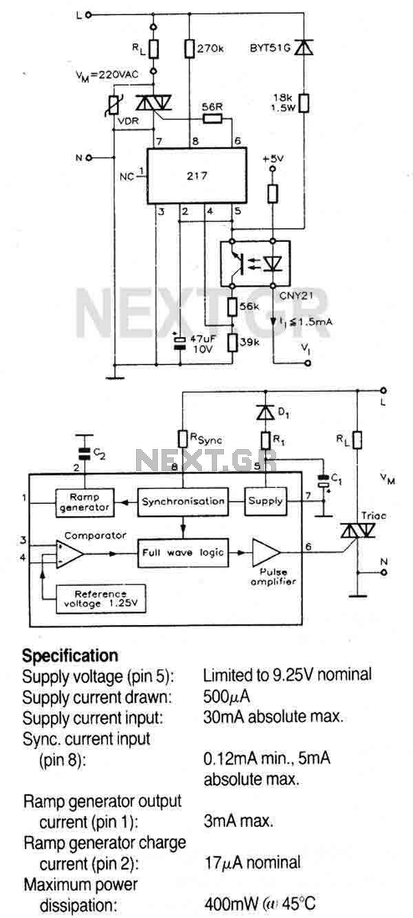
Temperature Controller with U217B
A triac controller for switching resistive loads directly from the mains supply using the zero crossing technique. The device is powered directly from the mains via a diode and dropper resistor, and the IC has its own regulator to limit...

Three-Power-Level Triac Controller Circuit
Three power levels are provided by the two logic inputs of this enhanced circuit. R5, D4, D5, and O2 create a power supply for the logic integrated circuit. These components can be excluded if an alternative low voltage source is...
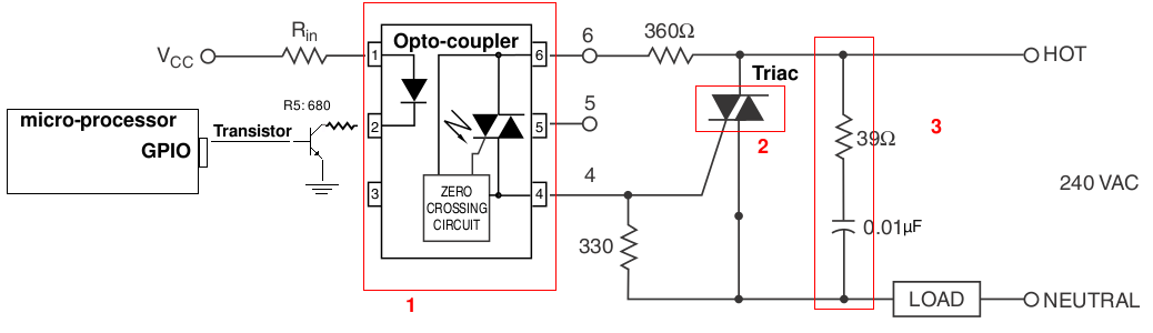
ac TRIAC dimmer circuit design help (resistive load)
A light-dimming control system is being developed for a 240V heat lamp with a power dissipation of approximately 250W. The objective is to adjust the heat output of the lamp using control from a microprocessor. The development is based on...
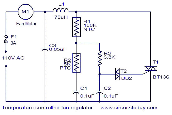
BT136 Temperature Controlled Fan Regulator
The function is designed to automatically control the speed of a fan based on the temperature. Components include a BT136 Triac, capacitor, resistor, relay, and fan motor.
The circuit employs a temperature sensing mechanism to monitor ambient temperature levels. A thermistor...
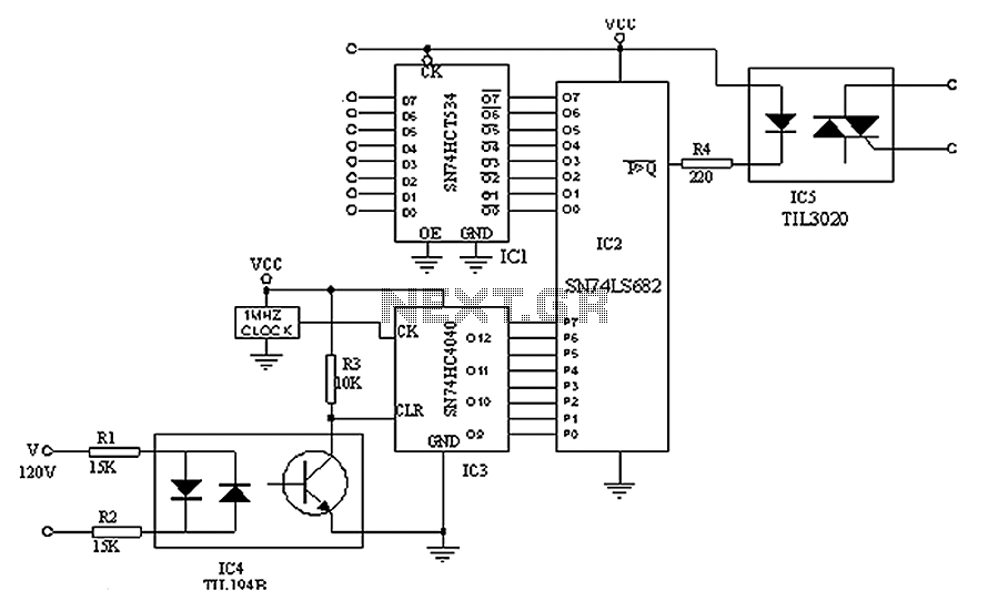
Digital triac circuit diagram
A simple digital circuit is presented that can be used to precisely control the AC power supply. This circuit does not include a digital-to-analog conversion component. In its application, effective control is established through a computer system that sends data...
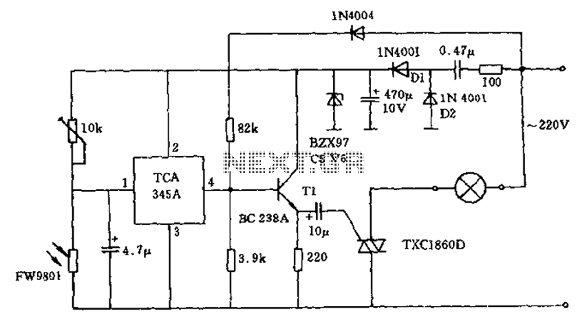
Triac lights automatically switch schematic
A 200W lamp switch control operates at a power supply voltage of 220V. It automatically turns the light on or off based on ambient illumination levels, specifically activating at approximately 100 lux. In low light conditions, a time-sensitive resistor exhibits...
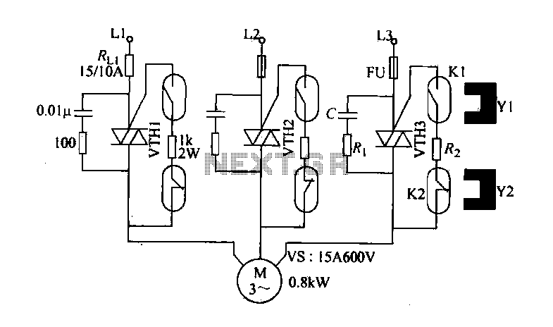
Cloth from idling stop saving circuit
The circuit diagram illustrates a female textile machine power control circuit. VTH1-VTH3 represent TRIACs, while R and C form the absorption line. Rz serves as the triggering current limiting resistor. K1 is designated for starting the reed, and K2 is...
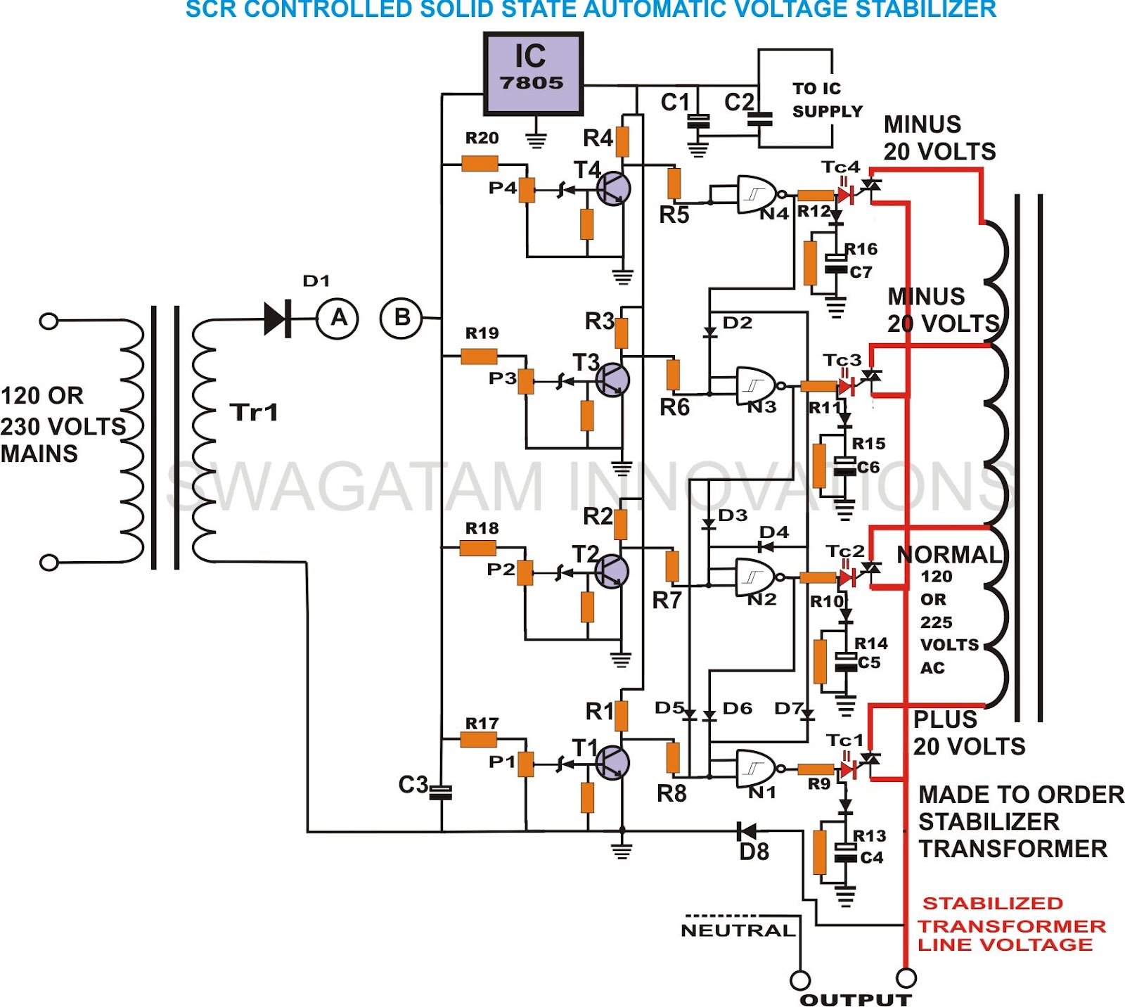
build solid state scrtriac controlled
This unique and hard-to-find triac-controlled AC voltage stabilizer circuit has been specifically designed for efficient voltage stabilization. With a solid-state design, the voltage switching transitions are smooth, resulting in minimal wear and tear. The proposed circuit provides four-step voltage stabilization...
Light Sensitive Staircase Switch with Triac
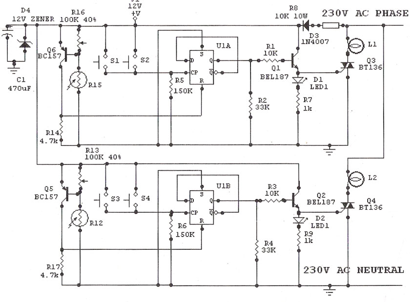
Light Sensitive Staircase Switch with Triac. The operation of the third circuit is similar, except that it incorporates photo sensitivity. The circuit is illustrated in the schematic. When there is insufficient light...
A light-sensitive staircase switch utilizing a TRIAC is designed...