


Power module unit diagram of IGBT and fly-wheel diode
#IGBT
#fly-wheel diode
#H bridge
#inverter
#chopping module
#three phase bridge
#half bridge
#single switch module
#braking chopper circuit
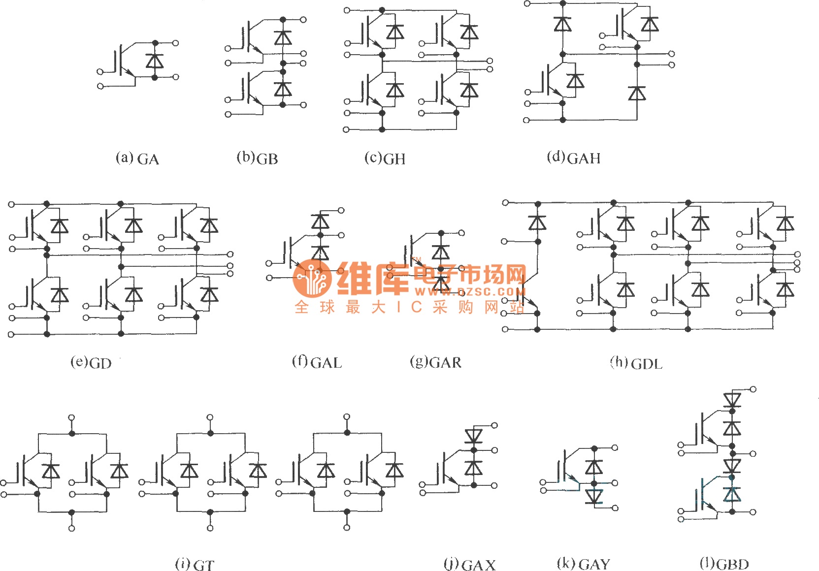
Description: This document describes various electronic modules, including: (a) a single switch module; (b) a two-unit half bridge module; (c) an H bridge (single-phase bridge) module; (d) an asymmetrical H bridge module; (e) a three-phase bridge (six-unit or inverter bridge) module; (f) a chopping module; (g) a second chopping module; (h) a three-phase bridge GD with an added chopping GAL (braking chopper circuit) module; (i) a three-unit module consisting of three group switches; (j) a single switch with a collector end series diode (negative direction disconnecting switch) module; (k) a single switch with an emitter end series diode (negative direction disconnecting switch) module; (l) a two-unit module with a series diode (negative direction disconnecting switch).
The electronic modules described serve various functions within power electronics and control systems.
The single switch module (a) is a basic building block for controlling power flow, typically used in applications requiring simple on/off functionality. The two-unit half bridge module (b) allows for the control of voltage across a load by switching two devices, effectively enabling bidirectional current flow.
The H bridge module (c) is essential for driving motors, as it allows for control of motor direction and speed by switching the polarity of the voltage applied to the motor. The asymmetrical H bridge module (d) provides similar functionality but is optimized for specific applications where one direction of current flow is more prevalent.
The three-phase bridge module (e) consists of six switching devices and is commonly used in three-phase motor drives and inverters, providing efficient power conversion and motor control. The chopping modules (f and g) are used for pulse-width modulation (PWM) techniques, which are crucial for controlling the output voltage and current in various applications, including DC-DC converters.
The three-phase bridge GD with chopping GAL (h) incorporates a braking chopper circuit, which is vital for regenerative braking applications, allowing energy to be fed back into the power supply during deceleration. The three-unit module (i) enhances flexibility and control by allowing multiple switches to be coordinated for complex power management tasks.
The single switch modules with series diodes (j, k, and l) are designed to prevent reverse current flow, thus ensuring protection of the circuit components. The collector end series diode (j) and emitter end series diode (k) configurations provide distinct advantages depending on the specific circuit design requirements. The two-unit module with a series diode (l) offers additional redundancy and reliability in applications where disconnecting switches are necessary for safe operation.
Overall, these modules are integral to modern electronic systems, facilitating efficient power management, control, and protection in a wide array of applications.Is single switch module; (b) is two unit (half bridge) module; (c) is H bridge (single phase bridge) module; (d) is asymmetrical H bridge module; (e) is three phase bridge (six unit or inverter bridge) module; (f) is chopping module (g) is chopping module (h) is three phase bridge GD add chopping GAL (braking chopper circuit) module; (i) is three unit module, consists of three group switch; (j) is single switch add collector end series diode ( negative direction disconnecting switch) module; (k) is single switch add emitter end series diode (negative direction disconnecting switch) module; (l) is two unit module, with series diode (negative direction disconnecting switch).
The electronic modules described serve various functions within power electronics and control systems.
The single switch module (a) is a basic building block for controlling power flow, typically used in applications requiring simple on/off functionality. The two-unit half bridge module (b) allows for the control of voltage across a load by switching two devices, effectively enabling bidirectional current flow.
The H bridge module (c) is essential for driving motors, as it allows for control of motor direction and speed by switching the polarity of the voltage applied to the motor. The asymmetrical H bridge module (d) provides similar functionality but is optimized for specific applications where one direction of current flow is more prevalent.
The three-phase bridge module (e) consists of six switching devices and is commonly used in three-phase motor drives and inverters, providing efficient power conversion and motor control. The chopping modules (f and g) are used for pulse-width modulation (PWM) techniques, which are crucial for controlling the output voltage and current in various applications, including DC-DC converters.
The three-phase bridge GD with chopping GAL (h) incorporates a braking chopper circuit, which is vital for regenerative braking applications, allowing energy to be fed back into the power supply during deceleration. The three-unit module (i) enhances flexibility and control by allowing multiple switches to be coordinated for complex power management tasks.
The single switch modules with series diodes (j, k, and l) are designed to prevent reverse current flow, thus ensuring protection of the circuit components. The collector end series diode (j) and emitter end series diode (k) configurations provide distinct advantages depending on the specific circuit design requirements. The two-unit module with a series diode (l) offers additional redundancy and reliability in applications where disconnecting switches are necessary for safe operation.
Overall, these modules are integral to modern electronic systems, facilitating efficient power management, control, and protection in a wide array of applications.Is single switch module; (b) is two unit (half bridge) module; (c) is H bridge (single phase bridge) module; (d) is asymmetrical H bridge module; (e) is three phase bridge (six unit or inverter bridge) module; (f) is chopping module (g) is chopping module (h) is three phase bridge GD add chopping GAL (braking chopper circuit) module; (i) is three unit module, consists of three group switch; (j) is single switch add collector end series diode ( negative direction disconnecting switch) module; (k) is single switch add emitter end series diode (negative direction disconnecting switch) module; (l) is two unit module, with series diode (negative direction disconnecting switch).
protect igbts sensing current using optical isolation amplifiers
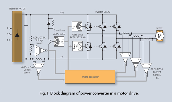
Isolation amplifiers provide an effective method to protect IGBTs against over-current, overload, and overvoltage conditions in addition to their current/voltage sensing function. Using these devices together with feature-rich gate drivers, a cost-effective yet comprehensive IGBT protection scheme can be implemented.
Isolation...
3000w inverter
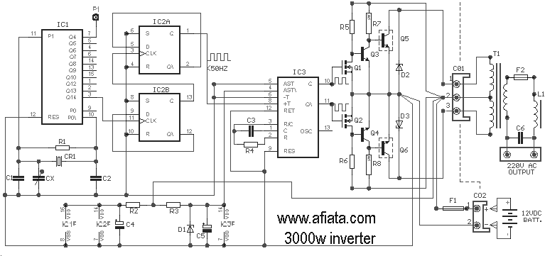
The inverter circuit is appreciated, and there is a request for detailed functionality of IC1 and IC2 in the 3000W inverter circuit. The individual expresses gratitude for the schematic diagram and seeks assistance in building the transformer, including specifications for...
Inverter size strength
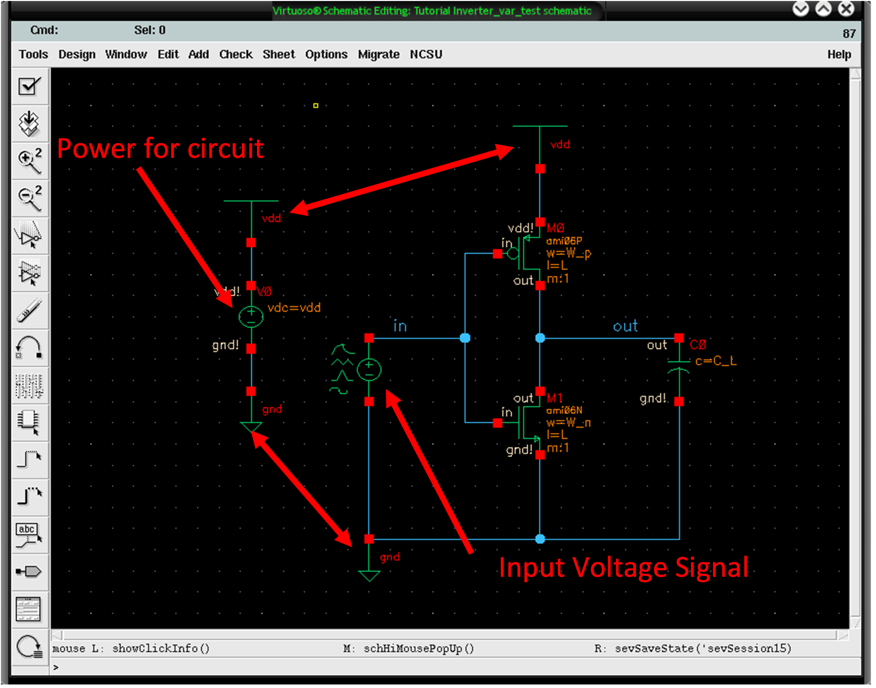
The differences in strengths between PMOS and NMOS transistors can be observed through a simple test by gradually increasing the input voltage and noting the point at which the output voltage changes from 5V to 0V. To conduct this test,...
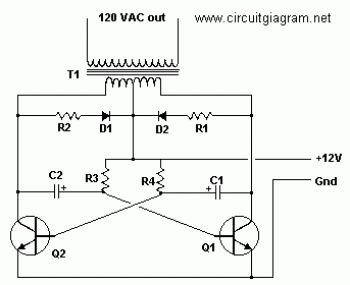
Basic Inverter
Q1 and Q2, along with T1, determine the wattage output of the inverter. Using Q1 and Q2 as 2N3055 transistors and T1 rated at 15 A, the inverter can provide approximately 300 watts. Substituting larger transformers and more powerful transistors...
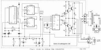
50W Inverter 12VDC to 220VAC circuit diagram
The objective is to transmit additional information through the distribution of articles. Please contact us via email at [email protected] within 15 days if there are any issues related to article content, copyright, or other concerns. Prompt action will be taken...
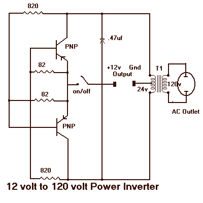
12 to 120 Volt Inverter
It will supply 15 watts of AC power to a device. It should power lamps, shavers, small stereos and small appliances. If you draw too much power the circuit will shut down all by itself. The output of this circuit...
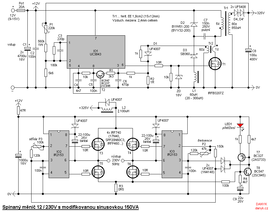
Switching (transformerless) DC/AC 12V/230V 150W modified sine wave inverter
The inverter is designed for powering mains appliances using battery sources. It functions as a switching converter, eliminating the need for bulky, heavy, and costly iron transformers. This design provides advantages such as compact size, lightweight construction, precise output voltage...
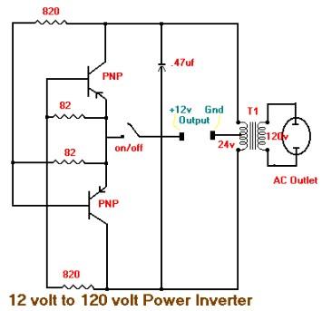
15W Inverter Circuit 12VDC to 120VAC
This is the schematic diagram of a 15W inverter circuit. The circuit is based on a PNP power transistor such as the TIP32 and other similar transistors. This inverter produces a square wave output, which may cause some noticeable hum...
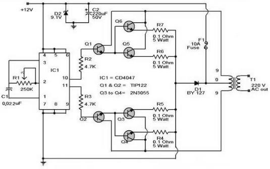
100W Inverter Circuit 12VDC to 220VAC
The schematic diagram of a 100W inverter circuit converts a 12V DC input into a 220V AC output. The circuit is built using the IC CD4047 to generate a 50Hz sine wave signal. The power transistor 2N3055 amplifies the signal...