


relay How can i drive a 5v 120VAC 80mA with 15A contacts with a raspberry pi
#raspberry pi
#relay
#latching relay
#home appliances
#5V
#120VAC
#current limit
#driver circuit
#control circuit
#switching
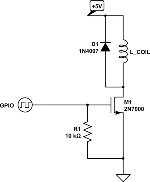
Description: Control a latching relay that requires approximately 70-90mA, while the Raspberry Pi can supply only about 40mA. A relay suitable for managing home appliances is needed, which can also be operated by the Raspberry Pi.
To achieve control over a latching relay with a current requirement of 70-90mA using a Raspberry Pi, which can only provide around 40mA, an interface circuit must be employed. This circuit typically involves using a transistor or a MOSFET as a switch to amplify the current from the Raspberry Pi.
A common approach is to use an NPN transistor such as the 2N2222 or a suitable MOSFET. The Raspberry Pi GPIO pin can be connected to the base of the NPN transistor through a current-limiting resistor, typically in the range of 1kΩ to 10kΩ. This resistor ensures that the GPIO pin is not overloaded while providing enough base current to turn the transistor on.
The collector of the NPN transistor will be connected to one side of the latching relay coil, while the other side of the coil connects to the positive supply voltage (typically 5V or 12V, depending on the relay specifications). A flyback diode, such as the 1N4001, should be placed in parallel with the relay coil to protect the circuit from back EMF generated when the relay is de-energized.
When the GPIO pin is set high, the transistor will turn on, allowing current to flow through the relay coil, thus energizing it. This will switch the relay, allowing it to control higher power loads, such as home appliances, without directly connecting them to the Raspberry Pi.
It is important to select a relay that can handle the specific voltage and current requirements of the home appliances intended to be controlled. Relays are available in various configurations, including single-pole single-throw (SPST) or double-pole double-throw (DPDT), allowing for flexibility in the application.
In summary, by utilizing a transistor as a current amplifier and ensuring proper protection with a flyback diode, a Raspberry Pi can effectively control a latching relay capable of handling home appliances, despite its limited current output.Drive a latching relay that needs about 70-90mA if the raspberry pi can only deliver about 40mA. I need to find a relay that can handle home appliances but can be controlled by the raspberry pi.
To achieve control over a latching relay with a current requirement of 70-90mA using a Raspberry Pi, which can only provide around 40mA, an interface circuit must be employed. This circuit typically involves using a transistor or a MOSFET as a switch to amplify the current from the Raspberry Pi.
A common approach is to use an NPN transistor such as the 2N2222 or a suitable MOSFET. The Raspberry Pi GPIO pin can be connected to the base of the NPN transistor through a current-limiting resistor, typically in the range of 1kΩ to 10kΩ. This resistor ensures that the GPIO pin is not overloaded while providing enough base current to turn the transistor on.
The collector of the NPN transistor will be connected to one side of the latching relay coil, while the other side of the coil connects to the positive supply voltage (typically 5V or 12V, depending on the relay specifications). A flyback diode, such as the 1N4001, should be placed in parallel with the relay coil to protect the circuit from back EMF generated when the relay is de-energized.
When the GPIO pin is set high, the transistor will turn on, allowing current to flow through the relay coil, thus energizing it. This will switch the relay, allowing it to control higher power loads, such as home appliances, without directly connecting them to the Raspberry Pi.
It is important to select a relay that can handle the specific voltage and current requirements of the home appliances intended to be controlled. Relays are available in various configurations, including single-pole single-throw (SPST) or double-pole double-throw (DPDT), allowing for flexibility in the application.
In summary, by utilizing a transistor as a current amplifier and ensuring proper protection with a flyback diode, a Raspberry Pi can effectively control a latching relay capable of handling home appliances, despite its limited current output.Drive a latching relay that needs about 70-90mA if the raspberry pi can only deliver about 40mA. I need to find a relay that can handle home appliances but can be controlled by the raspberry pi.
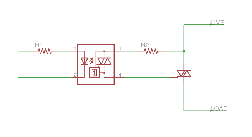
raspberry pi thermostat hookups
This document outlines the hardware connections between a Raspberry Pi and household wiring, specifically for controlling HVAC systems. In typical residential setups, thermostat wiring operates at 24V AC, with one or two live wires entering the thermostat and multiple wires...
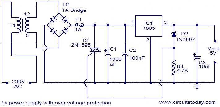
5V power supply with overvoltage protection
For circuits using TTL ICs, the supply voltage is a significant concern, as even a slight increase from the rated 5V can damage the IC. Relying solely on fuses is insufficient since a fuse may take several milliseconds to blow,...
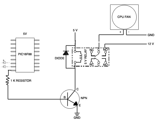
Pulsing Relay
A new member has joined the forum seeking assistance with a project involving the control of a CPU fan using a relay that is triggered by a stretch sensor. The circuit is currently set up, but the stretch sensor is...
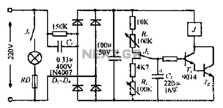
Lantern making use of a relay control circuit
220V mains electricity is sent through a 0.33 µF capacitor (Ci) and a 50 kΩ resistive drop. A bridge rectifier composed of diodes D1 to D4 converts the AC voltage to DC. After passing through a 100 µF capacitor for...
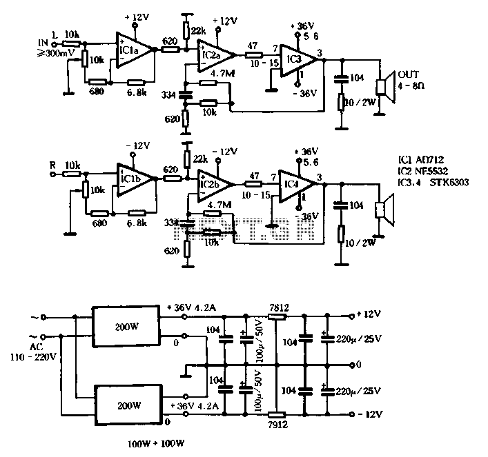
Switching power supply circuit with STK6303
The T amplifier circuit schematic section is illustrated in Figure 3-51. It utilizes the Japan Sanyo STK6303 Pina, which is a high-power thick film integrated circuit. The maximum power supply voltage is 36V, and the output current can reach approximately...
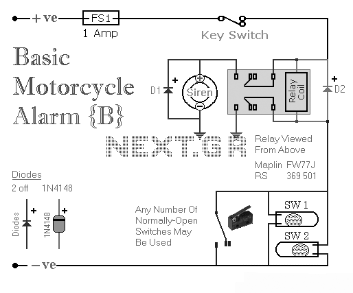
Two Simple Relay Based Motorcycle Alarms
Two simple relay-based motorcycle alarm circuits. These are easy to build and can be used to protect motorcycles, but they also have many other applications. If relays with 6-volt coils are used...
The motorcycle alarm circuits described consist of two basic...
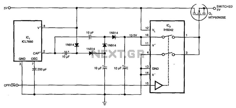
5V Supply High-Side Switcher
Requiring only 10 µA of quiescent current, the circuit produces an ON-resistance of only 0.1 ohm. IC1 serves as a charge pump voltage converter to generate a 5V level, allowing analog switch IC2 to provide a 10V swing to MOSFET...
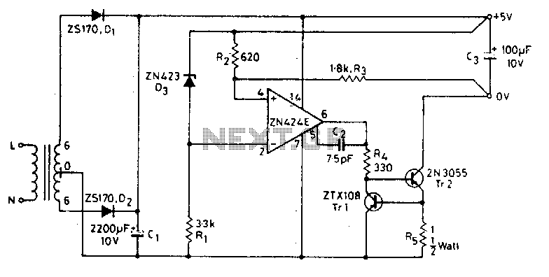
5V 0.5A power supply
The circuit functions as a constant voltage source, modified by feedback components R2 and R3 to maintain a stable output voltage. The ZN424E output must be at least 2 volts above the negative rail, with the load connected to the...

13.8V 40A Switching Power Supply By LM3524 and LM324 PCB
This article was originally published in a slightly modified form in the QST magazine, December 1998 and January 1999, and in the Radio Amateur's Handbook, 1999. Visit the American Radio Relay League for information on these publications and a world...