


Touch Switches Collection
#touch switch
#DIY electronics
#capacitance
#leakage
#hum pickup
#albedo
#sensor
#home automation
#reliability

Description: Touch operated switches are an attractive project for DIY electronics but they are not so common in commercial products. The reason for this is that, although there are many different ways of implementing a touch switch (leakage, hum pickup, capacitance, albedo), all of them rely on body parameters which vary a lot with the person's body, age, and environment so that a circuit which gives reliable operation with one development engineer may cause problems in use with, for instance, old folks living in arid areas. Nevertheless, touch switches can give excellent results.
This one is the equivalent to those banks of push buttons where you push any switch and it releases one already pushed in. I've only shown two stages but you can have 5 - or ten if you wish. Consider the state with the first stage on. Current flows from the 0V line through the 1K resistor, the LED, and the bottom two transistors. The center line will then be at about -10V.
Now touch input 2. The top transistor will pass current into the bottom transistor: the two bottom transistors will turn each other hard and suddenly on. But the 100n capacitor has no voltage across it so it takes a pulse of current as it charges up. Instantaneously the center line drops to -12V and the LED which was on extinguishes. Since the current that was flowing through this LED also flowed through the first pair, these turn off. The first 'button' has been released. Quite a nice, simple circuit for a multi-button touch switch. This is a timer or power switch. Touch the contacts and the switch turns on. After a preset delay, it turns off again. Its output is from a pass transistor so you can use it to operate another circuit during its timeout period. Touching the contacts causes a current to flow through the 4M7 into Tr3's base turning it on. Its collector current turns on Tr2. The 10µ capacitor is not charged, so it charges up, holding Tr3 on. Meanwhile, Tr2's emitter current turns on Tr1, applying power to the load.
While the 10µ is charging (determined by the 4M7 in series with it), the circuit stays on but when the 10µ is sufficiently charged, the current through it is too small to hold on Tr3 and the whole circuit turns off.
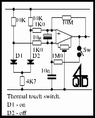
You can alter the timing by changing the 4M7 or the 10µ. This is an unusual touch switch that relies on the fact that the voltage drop in a diode is a function of its temperature. Warming the diode up reduces its voltage drop by about 2mV per degree centigrade (at room temperature).
The described touch switch circuit utilizes a combination of capacitive touch sensing and transistor switching to create a user-friendly interface for controlling devices. The operation begins when a user touches the designated area, which generates a small change in capacitance due to the proximity of the human body. This change is detected by the first stage of the circuit, comprised of a resistor and an LED, which indicates the state of the switch.
Once activated, the circuit uses a pair of transistors configured in a feedback loop. The first transistor receives the initial signal, which turns on the second transistor. This action creates a path for current to flow through the LED, illuminating it. The inclusion of a capacitor in the circuit is crucial, as it momentarily stores charge, allowing for a brief delay before the circuit resets, thereby giving the user visual feedback that the switch has been activated.
The timing mechanism is adjustable through the use of different resistor (4.7 MΩ) and capacitor (10 µF) values, allowing for customization based on the specific application requirements. The circuit can be used as a timer or power switch, where a touch will turn on the connected load, and after a predetermined delay, the load will turn off automatically.
In addition, the circuit incorporates a temperature-sensitive diode, which introduces an interesting characteristic to the switching behavior. As the diode heats up, its voltage drop decreases, influencing the performance of the circuit based on ambient temperature conditions. This feature can be utilized for applications requiring temperature compensation or for enhancing the sensitivity of the touch switch in varying environmental conditions. Overall, this touch switch circuit demonstrates a practical and innovative approach to user interface design within electronic projects.Touch operated switches are an attractive project for DIY electronics but they are not so common in commercial products. The reason for this is that, although there are many different ways of implementing a touch switch (leakage, hum pickup, capacitance, albedo) all of them rely on body parameters which vary a lot with the person's body, age and environment so that a circuit which gives reliable operation with one development engineer may cause problems in use with, for instance, old folks living in arid areas.
Nevertheless touch switches can give excellent results. This one is the equivalent to those banks of push buttons where you push any switch and it releases one already pushed in. I've only shown two stages but you can have 5 - or ten if you wish. Consider the state with the first stage on. Current flows from the 0v line through the 1K resistor, the LED and the bottom two transistors. The centre line will then be at about -10v. Now touch input 2. The top transistor will pass current into the bottom transistor: the two bottom transistors will turn each other hard and suddenly on.
But the 100n capacitor has no voltage across it so it takes a pulse of current as it charges up. Instantaneously he centre line drops to -12v and the LED which was on extinguishes. Since the current that was flowing through this LED also flowed through the first pair, these turn off. The first 'button' has been released. Quite a nice, simple circuit for a multi button touch switch. This is a timer or power switch. Touch the contacts and the switch turns on. After a preset delay it turns off again. Its output is from a pass transistor so you can use it to operate another circuit during its timeout period.
Touching the contacts causes a current to flow through the 4M7 into Tr3's base turning it on. Its collector current turns on Tr2. The 10µ capacitor is not charged, so it charges up, holding Tr3 on. Meanwhile Tr2's emitter current turns on Tr1, applying power to the load. While the 10µ is charging (determined by the 4M7 in series with it) the circuit stays on but when the 10µ is sufficiently charged the current through it is too small to hold on Tr3 and the whole circuit turns off. You can alter the timing by changing the 4M7 or the 10µ. This is an unusual touch switch that relies on the fact that the voltage drop in a diode is a function of its temperature.
Warming the diode up reduces its voltage drop by about 2mV per degree centigrade (at room temperature).
This one is the equivalent to those banks of push buttons where you push any switch and it releases one already pushed in. I've only shown two stages but you can have 5 - or ten if you wish. Consider the state with the first stage on. Current flows from the 0V line through the 1K resistor, the LED, and the bottom two transistors. The center line will then be at about -10V.
Now touch input 2. The top transistor will pass current into the bottom transistor: the two bottom transistors will turn each other hard and suddenly on. But the 100n capacitor has no voltage across it so it takes a pulse of current as it charges up. Instantaneously the center line drops to -12V and the LED which was on extinguishes. Since the current that was flowing through this LED also flowed through the first pair, these turn off. The first 'button' has been released. Quite a nice, simple circuit for a multi-button touch switch. This is a timer or power switch. Touch the contacts and the switch turns on. After a preset delay, it turns off again. Its output is from a pass transistor so you can use it to operate another circuit during its timeout period. Touching the contacts causes a current to flow through the 4M7 into Tr3's base turning it on. Its collector current turns on Tr2. The 10µ capacitor is not charged, so it charges up, holding Tr3 on. Meanwhile, Tr2's emitter current turns on Tr1, applying power to the load.
While the 10µ is charging (determined by the 4M7 in series with it), the circuit stays on but when the 10µ is sufficiently charged, the current through it is too small to hold on Tr3 and the whole circuit turns off.
You can alter the timing by changing the 4M7 or the 10µ. This is an unusual touch switch that relies on the fact that the voltage drop in a diode is a function of its temperature. Warming the diode up reduces its voltage drop by about 2mV per degree centigrade (at room temperature).
The described touch switch circuit utilizes a combination of capacitive touch sensing and transistor switching to create a user-friendly interface for controlling devices. The operation begins when a user touches the designated area, which generates a small change in capacitance due to the proximity of the human body. This change is detected by the first stage of the circuit, comprised of a resistor and an LED, which indicates the state of the switch.
Once activated, the circuit uses a pair of transistors configured in a feedback loop. The first transistor receives the initial signal, which turns on the second transistor. This action creates a path for current to flow through the LED, illuminating it. The inclusion of a capacitor in the circuit is crucial, as it momentarily stores charge, allowing for a brief delay before the circuit resets, thereby giving the user visual feedback that the switch has been activated.
The timing mechanism is adjustable through the use of different resistor (4.7 MΩ) and capacitor (10 µF) values, allowing for customization based on the specific application requirements. The circuit can be used as a timer or power switch, where a touch will turn on the connected load, and after a predetermined delay, the load will turn off automatically.
In addition, the circuit incorporates a temperature-sensitive diode, which introduces an interesting characteristic to the switching behavior. As the diode heats up, its voltage drop decreases, influencing the performance of the circuit based on ambient temperature conditions. This feature can be utilized for applications requiring temperature compensation or for enhancing the sensitivity of the touch switch in varying environmental conditions. Overall, this touch switch circuit demonstrates a practical and innovative approach to user interface design within electronic projects.Touch operated switches are an attractive project for DIY electronics but they are not so common in commercial products. The reason for this is that, although there are many different ways of implementing a touch switch (leakage, hum pickup, capacitance, albedo) all of them rely on body parameters which vary a lot with the person's body, age and environment so that a circuit which gives reliable operation with one development engineer may cause problems in use with, for instance, old folks living in arid areas.
Nevertheless touch switches can give excellent results. This one is the equivalent to those banks of push buttons where you push any switch and it releases one already pushed in. I've only shown two stages but you can have 5 - or ten if you wish. Consider the state with the first stage on. Current flows from the 0v line through the 1K resistor, the LED and the bottom two transistors. The centre line will then be at about -10v. Now touch input 2. The top transistor will pass current into the bottom transistor: the two bottom transistors will turn each other hard and suddenly on.
But the 100n capacitor has no voltage across it so it takes a pulse of current as it charges up. Instantaneously he centre line drops to -12v and the LED which was on extinguishes. Since the current that was flowing through this LED also flowed through the first pair, these turn off. The first 'button' has been released. Quite a nice, simple circuit for a multi button touch switch. This is a timer or power switch. Touch the contacts and the switch turns on. After a preset delay it turns off again. Its output is from a pass transistor so you can use it to operate another circuit during its timeout period.
Touching the contacts causes a current to flow through the 4M7 into Tr3's base turning it on. Its collector current turns on Tr2. The 10µ capacitor is not charged, so it charges up, holding Tr3 on. Meanwhile Tr2's emitter current turns on Tr1, applying power to the load. While the 10µ is charging (determined by the 4M7 in series with it) the circuit stays on but when the 10µ is sufficiently charged the current through it is too small to hold on Tr3 and the whole circuit turns off. You can alter the timing by changing the 4M7 or the 10µ. This is an unusual touch switch that relies on the fact that the voltage drop in a diode is a function of its temperature.
Warming the diode up reduces its voltage drop by about 2mV per degree centigrade (at room temperature).
On/Off Touch Switch
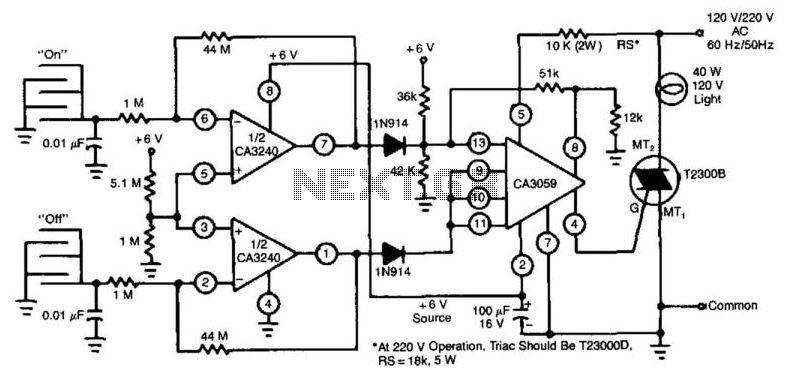
This circuit employs a CA3240 dual BiMOS operational amplifier to detect small currents that flow between the contact points on a touch plate. The high input impedance of the CA3240 enables the use of 1-megaohm resistors in series with the...
capacity Computing Current from known Capacitance and Time to Charge to Known Voltage
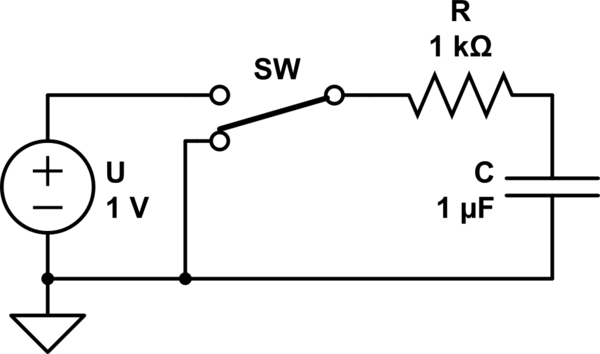
Consider a capacitor with capacitance C that charges to a voltage V and discharges to 0V at a frequency of 5 times per second. To estimate the average current, also referred to as the RMS current, a rough approximation can...
Touch Switch Circuits
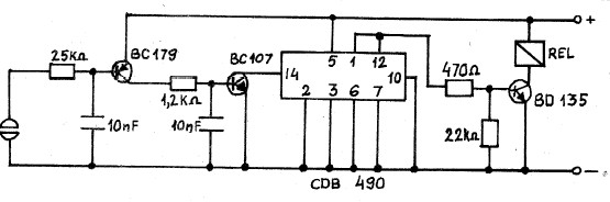
A collection of touch switch circuits is presented. A touch switch is an electronic device that allows control of a circuit simply by touching a sensor. The circuit diagram illustrates a simple design that utilizes only eight components. The core...
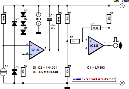
Electronic Touch Switch
Mechanical contacts have the disadvantage of wearing out. Therefore, it is practical to use an electronic touch switch in certain situations. This type of touch switch utilizes the resistance of human skin for its switching action. The schematic illustrates a...
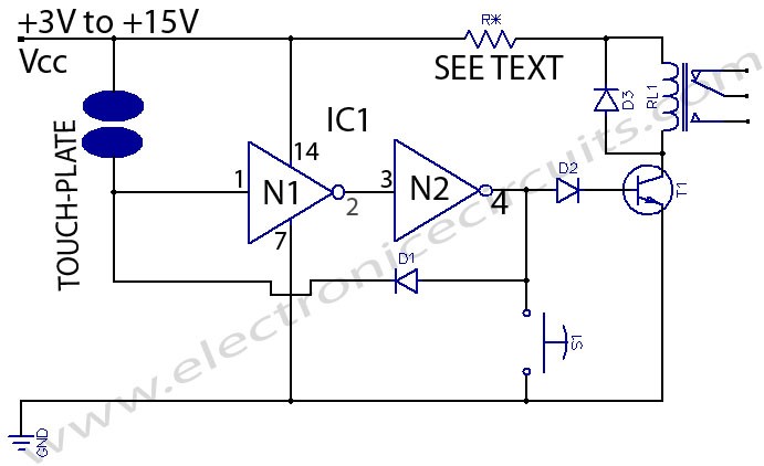
Touch Switch
This is a touch switch designed to control LEDs, relays, and similar devices through a buffer transistor stage. It can be constructed using any CMOS inverter chip.
The touch switch circuit operates by utilizing the capacitive touch sensing principle, which allows...
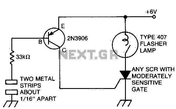
Capacitance switched light
The battery-powered light activates with ease, remaining illuminated for a few seconds before automatically shutting off. The circuit is engaged when a finger bridges the gap between two metal strips, approximately 1/16 inch apart. Sufficient current flows through the finger...
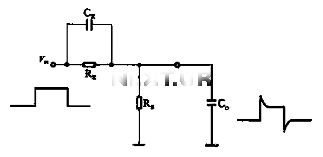
Accelerate the role of capacitance
Accelerate the role of capacitance to reduce the delay of the waveform. In parallel with the signal input resistor RK, a speed-up capacitor CK is used to sharpen the pulse edge, thereby reducing the impact of small input capacitance.
In electronic...
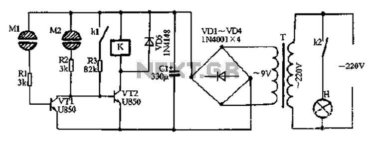
Two-way touch switch 4
After the power is turned on, 220V AC is stepped down by transformer T. The output is then rectified by the VD1 to VD4 bridge rectifier and filtered by C1 to produce approximately 10V DC voltage for the Darlington circuit...
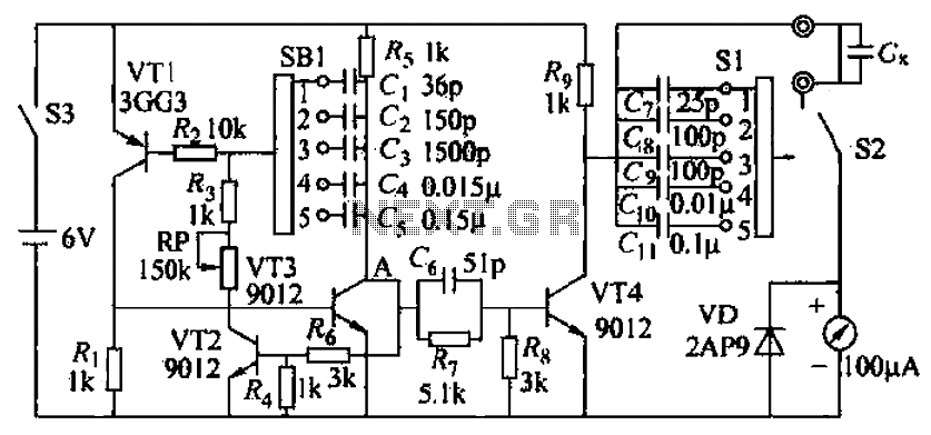
A capacitance measuring circuit
A capacitive measuring instrument is a direct reading device that measures the capacitance of a circuit. This instrument is capable of measuring capacitance values ranging from a few picofarads to 0.1 microfarads, with specific ranges of 25 pF, 100 pF,...