


Color TV Camera Tutorial - Block Diagrams
#TV camera
#modulation
#carrier wave
#block diagram
#electronics tutorial
#hobby projects
#signal processing
#video transmission
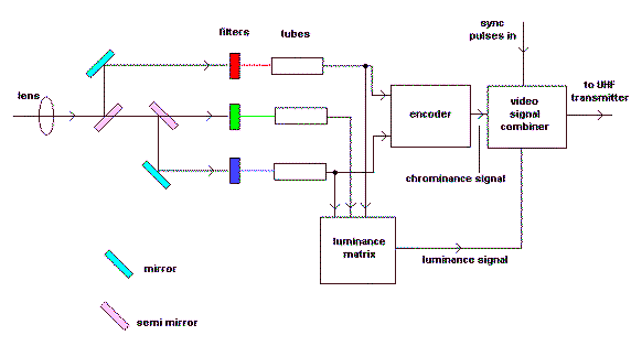
Description: Colour TV Camera Tutorial - Block Diagrams - Electronics Circuit and Tutorials - Hobby Science Projects - Modulation allows low-frequency audio signals to be transmitted over long distances. This is achieved by superimposing the low-frequency audio signal onto a high-frequency carrier wave through the modulation process.
The Colour TV Camera tutorial encompasses various aspects of electronic circuit design, particularly focusing on block diagrams that illustrate the fundamental operation of a color television camera system. The modulation technique is crucial in this context, as it facilitates the transmission of audio signals over considerable distances.
In a typical color TV camera, the system can be divided into several functional blocks: the lens system, image sensor, signal processing unit, modulation circuit, and transmission module. The lens system captures the light from the scene and focuses it onto the image sensor, which converts the optical signals into electrical signals.
The image sensor typically consists of a charge-coupled device (CCD) or a complementary metal-oxide-semiconductor (CMOS) sensor, which is responsible for converting the light intensity into voltage levels corresponding to the brightness of the image. The output from the image sensor is a series of analog signals that represent the captured image.
Following this, the signal processing unit enhances and prepares these signals for modulation. This unit may include amplifiers, filters, and analog-to-digital converters (ADCs) to improve signal quality and convert the analog signals into a digital format for further processing.
The modulation circuit then takes the processed audio and video signals and combines them with a high-frequency carrier wave. This is performed using techniques such as amplitude modulation (AM) or frequency modulation (FM), where the low-frequency audio signal is superimposed onto the carrier wave. The modulation process is essential for enabling the transmission of audio signals alongside video signals, ensuring that both can be sent over the same medium without interference.
Finally, the transmission module broadcasts the modulated signals over the airwaves, allowing them to be received by compatible television sets. The receiving end demodulates the signals, extracting the audio and video components for display.
This comprehensive understanding of the color TV camera system and its modulation process is vital for hobbyists and professionals engaged in electronics projects and telecommunications. The block diagrams serve as an effective visual aid, simplifying the complex interactions between the various components involved in the operation of color TV cameras.Colour TV Camera Tutorial - Block Diagrams - Electronics Circuit and Tutorials - Hobby Science Projects - Modulation enables low frequency audio signals to be radiated long distances. This is done by superimposing the low frequency audio signal on the high frequency carrier wave by the process of modulation
The Colour TV Camera tutorial encompasses various aspects of electronic circuit design, particularly focusing on block diagrams that illustrate the fundamental operation of a color television camera system. The modulation technique is crucial in this context, as it facilitates the transmission of audio signals over considerable distances.
In a typical color TV camera, the system can be divided into several functional blocks: the lens system, image sensor, signal processing unit, modulation circuit, and transmission module. The lens system captures the light from the scene and focuses it onto the image sensor, which converts the optical signals into electrical signals.
The image sensor typically consists of a charge-coupled device (CCD) or a complementary metal-oxide-semiconductor (CMOS) sensor, which is responsible for converting the light intensity into voltage levels corresponding to the brightness of the image. The output from the image sensor is a series of analog signals that represent the captured image.
Following this, the signal processing unit enhances and prepares these signals for modulation. This unit may include amplifiers, filters, and analog-to-digital converters (ADCs) to improve signal quality and convert the analog signals into a digital format for further processing.
The modulation circuit then takes the processed audio and video signals and combines them with a high-frequency carrier wave. This is performed using techniques such as amplitude modulation (AM) or frequency modulation (FM), where the low-frequency audio signal is superimposed onto the carrier wave. The modulation process is essential for enabling the transmission of audio signals alongside video signals, ensuring that both can be sent over the same medium without interference.
Finally, the transmission module broadcasts the modulated signals over the airwaves, allowing them to be received by compatible television sets. The receiving end demodulates the signals, extracting the audio and video components for display.
This comprehensive understanding of the color TV camera system and its modulation process is vital for hobbyists and professionals engaged in electronics projects and telecommunications. The block diagrams serve as an effective visual aid, simplifying the complex interactions between the various components involved in the operation of color TV cameras.Colour TV Camera Tutorial - Block Diagrams - Electronics Circuit and Tutorials - Hobby Science Projects - Modulation enables low frequency audio signals to be radiated long distances. This is done by superimposing the low frequency audio signal on the high frequency carrier wave by the process of modulation
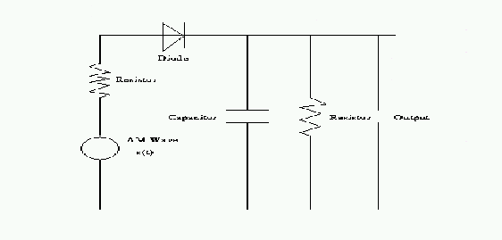
modulation
A reason to modulate a message signal is to match the communication channel's frequency. This is necessary because the information to be sent over the channel is often at a relatively low frequency. For instance, the frequency range of music...
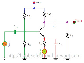
modulation is process of changing
Modulation is the process of altering certain characteristics (such as amplitude, frequency, or phase) of a carrier wave in accordance with the intensity of the signal. The provided figure illustrates the electronic circuit of a simple amplitude modulation (AM) modulator....
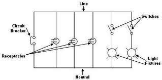
Electrical Single Line Diagram-Part One
Each component of the circuit is represented in a simple block form with corresponding labels for identification, using no special symbols or language. The interconnections between these components are depicted by solid lines. The block diagrams can be read from...
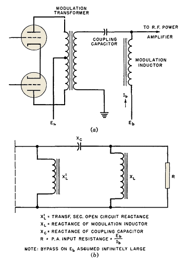
Electronic Transformers Modulation
Wave-filter principles are utilized in various circuits beyond filters, such as in the design of modulation transformers for high-level amplitude-modulated radio transmitters. Some of these transformers are quite large. In plate-modulated power amplifiers, the modulator power necessary for achieving 100...
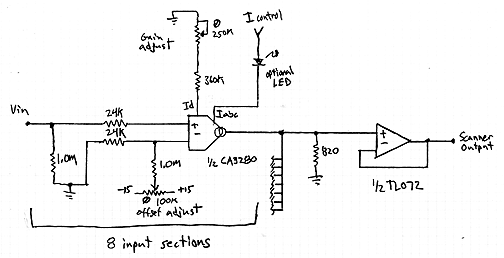
Interpolating Scanner Circuit
This design is for an interpolating scanner, a circuit featuring multiple signal inputs, a control voltage input, and a signal output. The output selectively transitions between inputs, smoothly fading from one to the next as the control voltage increases. A...
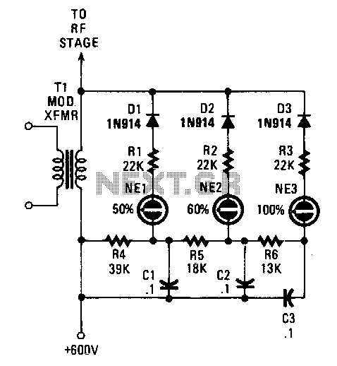
Modulation-monitor
Switching diodes are utilized to activate the neon lamps when negative-peak modulation reaches 50%, 60%, and 100%. To operate the circuit effectively, it is important to monitor the lamps. The 50% lamp should ideally be firing continuously, the 60% lamp...
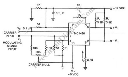
Double-Sideband Suppressed-Carrier (DSB-SC) Modulator
When a carrier signal is modulated using amplitude modulation, four frequency components are produced. The first component is the modulating signal itself, the second is the carrier frequency, while the last two are the sum and difference of the carrier...