


Examples OFDM modulation system circuit
#OFDM
#modulation
#data signal
#communication
#wireless
#digital signal processing
#RF
#telecommunication
#signal processing
Description: Examples of an OFDM modulation system. The graph illustrates the input data signal (.... --- Ol01100) and the data signal by the string. The input signal is separated into components such as "00", "ll", "10", "00", "01", and other data segments. The separated data undergoes positive change modulation along the time axis, resulting in the formation of Q amplitude components. These signals are processed through the Inverse Discrete Fourier Transform (IDFT), converting them into Q signals, which are then serialized to produce two orthogonal Q serial signals.
In an Orthogonal Frequency Division Multiplexing (OFDM) modulation system, the input data signal is first analyzed and separated into distinct binary components. The separation process identifies patterns in the data, such as "00", "ll", "10", "00", and "01". Each of these components represents a unique state of the original data signal. Following separation, the data is modulated through a positive change modulation process on the time axis, which adjusts the amplitude of the signal based on the input data.
The modulation process is crucial as it allows for the efficient encoding of data onto multiple subcarriers, enhancing the transmission efficiency and robustness against interference. The resulting amplitude components, referred to as Q components, are then subjected to an Inverse Discrete Fourier Transform (IDFT). This transformation is essential for converting the frequency domain representation of the modulated signals back into the time domain, facilitating the creation of two orthogonal Q serial signals.
These orthogonal signals are pivotal in OFDM systems as they allow for simultaneous transmission over multiple frequencies without causing interference with one another. The orthogonality of the signals ensures that they can be demodulated effectively at the receiver end, preserving the integrity of the transmitted data. The output of the system thus consists of two orthogonal Q serial signals, ready for transmission over a communication channel, ensuring efficient and reliable data transfer.Examples OFDM modulation system. Seen from the graph, the input data signal (... --- Ol01100), the data signal by the string, and converts the input signal is separated, separated into "00", "ll", "10", "00", "01 "and other data. Data separated further positive change modulation on the time axis are formed ,, Q amplitude components.
These signals are in the IDFT inverse discrete Fourier transformation. Converted into, and Q signals respectively and / serial conversion and then outputs two orthogonal ,, Q serial signal.
In an Orthogonal Frequency Division Multiplexing (OFDM) modulation system, the input data signal is first analyzed and separated into distinct binary components. The separation process identifies patterns in the data, such as "00", "ll", "10", "00", and "01". Each of these components represents a unique state of the original data signal. Following separation, the data is modulated through a positive change modulation process on the time axis, which adjusts the amplitude of the signal based on the input data.
The modulation process is crucial as it allows for the efficient encoding of data onto multiple subcarriers, enhancing the transmission efficiency and robustness against interference. The resulting amplitude components, referred to as Q components, are then subjected to an Inverse Discrete Fourier Transform (IDFT). This transformation is essential for converting the frequency domain representation of the modulated signals back into the time domain, facilitating the creation of two orthogonal Q serial signals.
These orthogonal signals are pivotal in OFDM systems as they allow for simultaneous transmission over multiple frequencies without causing interference with one another. The orthogonality of the signals ensures that they can be demodulated effectively at the receiver end, preserving the integrity of the transmitted data. The output of the system thus consists of two orthogonal Q serial signals, ready for transmission over a communication channel, ensuring efficient and reliable data transfer.Examples OFDM modulation system. Seen from the graph, the input data signal (... --- Ol01100), the data signal by the string, and converts the input signal is separated, separated into "00", "ll", "10", "00", "01 "and other data. Data separated further positive change modulation on the time axis are formed ,, Q amplitude components.
These signals are in the IDFT inverse discrete Fourier transformation. Converted into, and Q signals respectively and / serial conversion and then outputs two orthogonal ,, Q serial signal.
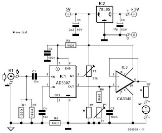
RF Decibel Meter
This is a zine dedicated to electronics circuit diagrams, DIY (do it yourself) electronics projects, electrical electronics data sheets, and microcontroller projects for hobbyists, students, consultants, and product designers.
The zine serves as a comprehensive resource for individuals interested in electronics,...
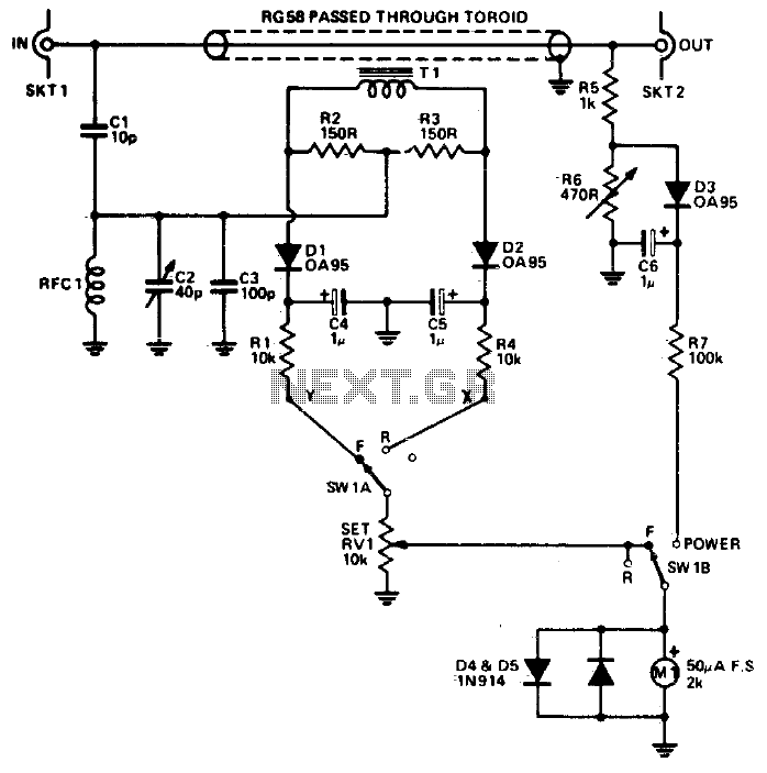
Rf power meter
The reflectometer (SWR power meter) operates across three decades, ranging from 100 kHz to 100 MHz. It can be designed to handle RF power levels as low as 500 mW and up to 500 watts.
The reflectometer, also known as a...

Transmitter RF Output LED Indicator
Transmitter RF Output LED Indicator Circuit Diagram. This RF output detector circuit, which includes a visual indicator, can be useful for an RF application.
The transmitter RF output LED indicator circuit is designed to provide a visual representation of the RF...
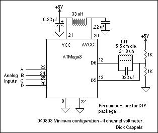
Wireless Coupled Scanning Voltmeter (ATMega8)
A 10 bit scanning voltmeter with a Minimum Mass Wireless Coupler, based on the ATMega8. Range to the Minimum Mass Base Unit is 10 to 15 cm. If the voltmeter is battery operated, it can be floated from ground. This...
Wireless Telephone Bug
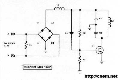
Wireless Telephone Bug. This project enables monitoring of a phone line as soon as the phone is off-hook. A regular FM broadcast band radio can be utilized for this purpose.
The Wireless Telephone Bug is a circuit designed to allow users...
Road remote control switch production
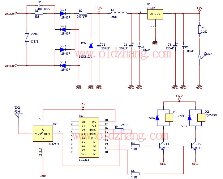
The production of this wireless remote control switch is relatively straightforward. All component parameters have been tested and verified. The installation of the reader component parameters can be completed during production, including the soldering of resistive and capacitive components onto...
One kind of wireless remote control circuit
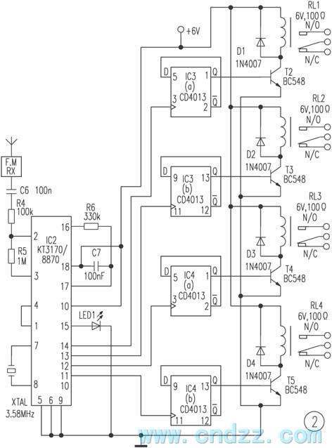
The remote control transmitter consists of a DTMF generator and an FM transmitter circuit. A UM91214B phone-specific integrated circuit (IC) is utilized to generate the DTMF signal, with a 3V power supply provided by a 3V zener diode (D1). The...
Wireless Car AlarmCircuit With 2N3904 Transistor
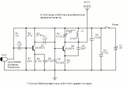
The following circuit illustrates a Wireless Car Alarm Circuit Schematic Diagram. Features include the ability to detect sounds within a 20-meter radius, a 1/16 wavelength antenna, and the capability to transmit radio signals up to 2 kilometers. Q1 serves as...
RF circuits
A field strength meter utilizing a biased Schottky detector employs a temperature-compensated Schottky diode within an amplified, untuned field strength indicator powered by two AA cells. This device indicates the relative field strength of RF fields ranging from a few...