


Limited TV channels to increase reception circuit
#TV tuner
#CATV
#signal reception
#AV output
#electronic tuner
#television
#broadcast
#RF signal
#channel selection
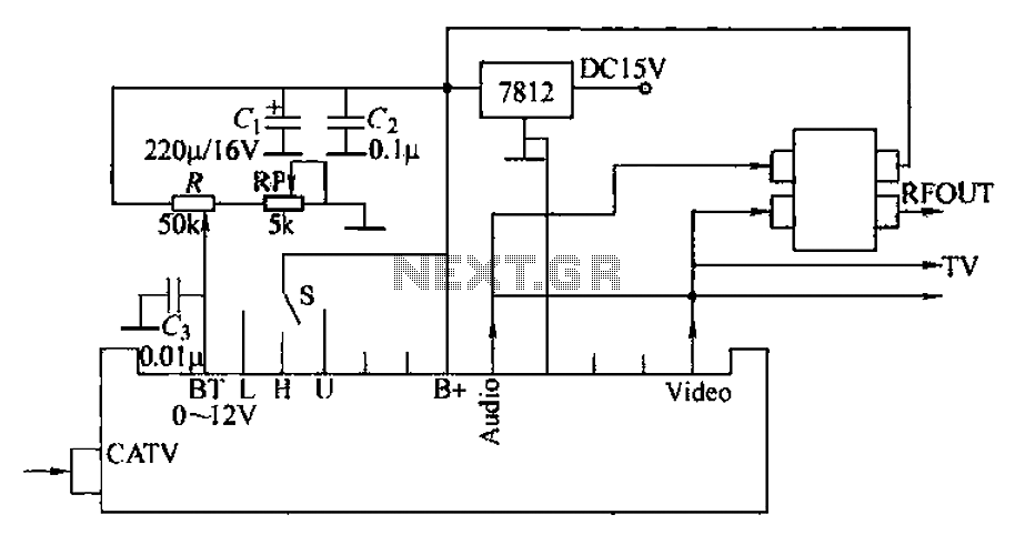
Description: The circuit utilizes two main components: an integrated electronic tuner with AV output, commonly referred to as the tuner, which can receive CATV full channel TV signals and output a video signal (Vttko) along with an audio signal (Audio). The second component is a signal modulator, which is a radio modulation device that modulates the audio and video signals onto a designated TV channel for viewing. The audio and video input ports of the TV do not require an external adjuster and can be directly connected to the sound tuner and video output. The circuit is illustrated in Figure 1-41, designed for S-band selection. An RP component is included for selection purposes. A 7812 three-terminal regulator is employed to generate a +12V voltage supply for the high-frequency head and demodulator.
The circuit described is designed for the reception and modulation of CATV signals, integrating an electronic tuner and a modulator for seamless output to a television. The electronic tuner acts as the primary interface for capturing full-channel CATV signals, processing them into usable audio and video outputs. The audio output is designated as 'Audio', while the video output is labeled 'Vttko'.
The signal modulator plays a crucial role in this setup, as it takes the processed audio and video signals and modulates them onto a specific television channel, enabling the viewer to access additional programming without the need for complex adjustments. The direct connection of the audio and video outputs to the television's input ports simplifies the user experience, allowing for straightforward integration into existing setups.
The circuit schematic, as referenced in Figure 1-41, is tailored for S-band selection, indicating its operational frequency range. The inclusion of an RP component facilitates the selection process, allowing users to choose the desired frequency or channel with ease.
Power management within the circuit is handled by a 7812 three-terminal voltage regulator, which is responsible for supplying a stable +12V output. This voltage is essential for powering the high-frequency head and the demodulator, ensuring that the circuit operates efficiently and reliably. The use of a three-terminal regulator simplifies the power supply design while providing consistent performance across the circuit's components.
Overall, this circuit design exemplifies an effective approach to integrating CATV signal reception and modulation, providing users with a reliable and user-friendly solution for enhanced television viewing experiences. Circuit uses two features: one is the integrated electronic tuner with AV output (commonly known as the tuner) which can be received CATV full channel TV signal into a final vi deo (Vttko) and an audio signal (Audio )} another component is a signal modulator (radio modulation device), it may sound, - video signal is modulated onto a TV channel by the television viewing additional channel program. Opponents audio and video input port of the TV, you can not shoot adjuster, directly connected to the sound tuner, video output.
Circuit shown in Figure 1-41, S-band for the death choice. RP thrown in selection. 7812 three-terminal regulator generates + 12V voltage supply respectively high frequency head and demodulator shot.
The circuit described is designed for the reception and modulation of CATV signals, integrating an electronic tuner and a modulator for seamless output to a television. The electronic tuner acts as the primary interface for capturing full-channel CATV signals, processing them into usable audio and video outputs. The audio output is designated as 'Audio', while the video output is labeled 'Vttko'.
The signal modulator plays a crucial role in this setup, as it takes the processed audio and video signals and modulates them onto a specific television channel, enabling the viewer to access additional programming without the need for complex adjustments. The direct connection of the audio and video outputs to the television's input ports simplifies the user experience, allowing for straightforward integration into existing setups.
The circuit schematic, as referenced in Figure 1-41, is tailored for S-band selection, indicating its operational frequency range. The inclusion of an RP component facilitates the selection process, allowing users to choose the desired frequency or channel with ease.
Power management within the circuit is handled by a 7812 three-terminal voltage regulator, which is responsible for supplying a stable +12V output. This voltage is essential for powering the high-frequency head and the demodulator, ensuring that the circuit operates efficiently and reliably. The use of a three-terminal regulator simplifies the power supply design while providing consistent performance across the circuit's components.
Overall, this circuit design exemplifies an effective approach to integrating CATV signal reception and modulation, providing users with a reliable and user-friendly solution for enhanced television viewing experiences. Circuit uses two features: one is the integrated electronic tuner with AV output (commonly known as the tuner) which can be received CATV full channel TV signal into a final vi deo (Vttko) and an audio signal (Audio )} another component is a signal modulator (radio modulation device), it may sound, - video signal is modulated onto a TV channel by the television viewing additional channel program. Opponents audio and video input port of the TV, you can not shoot adjuster, directly connected to the sound tuner, video output.
Circuit shown in Figure 1-41, S-band for the death choice. RP thrown in selection. 7812 three-terminal regulator generates + 12V voltage supply respectively high frequency head and demodulator shot.
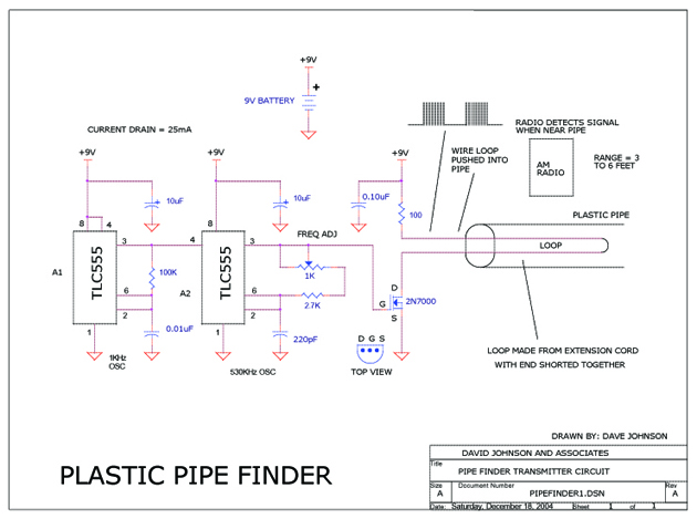
Plastic Pipe Finder
This circuit is designed to track the location of a plastic pipe buried underground. It transmits a weak RF signal that can be detected by a portable AM radio from a distance of approximately 6 feet.
The circuit operates by generating...

1-2Mhz broadcast transmitter
T1 is a low impedance output transformer with a conversion ratio of 5000 to 8 ohms.
The low impedance output transformer, T1, is designed to match the output of an audio amplifier to the impedance of the speaker load. The specified...
Fully Functional Television Oscilloscope
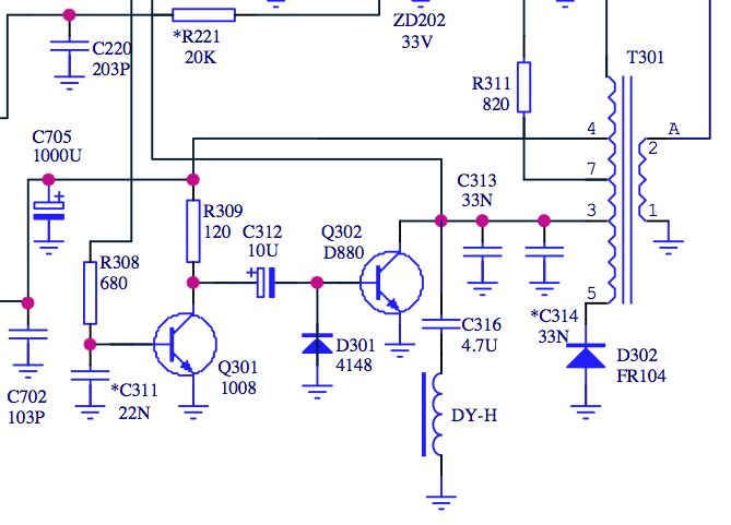
There are several Instructables and other internet-based instructions on how to modify a television set into an audio visualizer or other simple applications.
To transform a television set into an audio visualizer, a detailed understanding of both the television's hardware and...
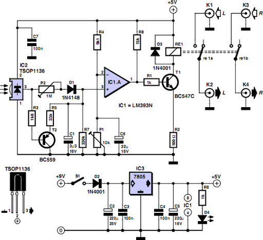
TV Muter Circuit
Many households still have tube-type television sets. Connecting one of these large televisions to a stereo system to enhance sound quality is generally straightforward, as numerous SCART to Cinch adapters are available in accessory stores. However, some television sets may...
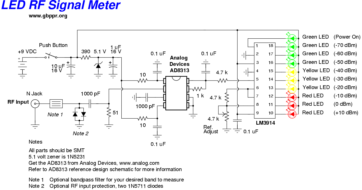
led rf signal meter
This RF Wave Absorption meter detects signals from 10 centimeters to 10 meters, depending on the setting of the 22 MegOhm gain adjustment potentiometer and the transmitter power. The RF signal is captured through germanium OA91 diodes and rectified to...
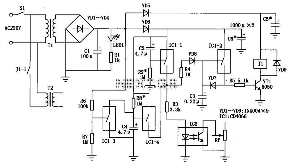
Cable broadcast amplifiers circuit protection
A cable radio broadcasting studio in rural villages and towns is often equipped with high-power amplifiers that are susceptible to damage. This vulnerability primarily arises from frequent usage without specialized management, leading to situations where the system is often powered...

Working Principle Television (TV)
Before studying the working principles of a TV receiver, it is important to understand the journey of the image displayed on the television. The images seen on TV are produced by a camera. The object image captured by the camera...
Circuit diagram of grundig 5441 tv
Circuit for Grundig 5441 TV. If there are any issues related to this circuit, please provide additional information about the problem for further assistance. By accessing the Fixya site, users acknowledge that they have read and agreed to its Terms....
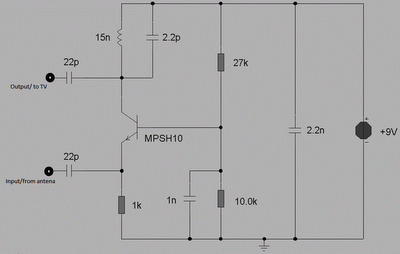
simple booster tv schematic diagram
This circuit is designed to enhance RF signals from a television antenna operating at UHF frequencies in the range of 450-800 MHz. It provides a gain of approximately 10 dB, making it suitable for boosting weak TV signals. The tuned...