


MD-1142/UGC Modem Time Diversity BR Communications 6029C Time Diversity Modem
#modem
#chirp sounder
#transmitter
#receiver
#order wire signal
#carrier
#BR Communications
#TCI
#Dielectric Inc
#time diversity
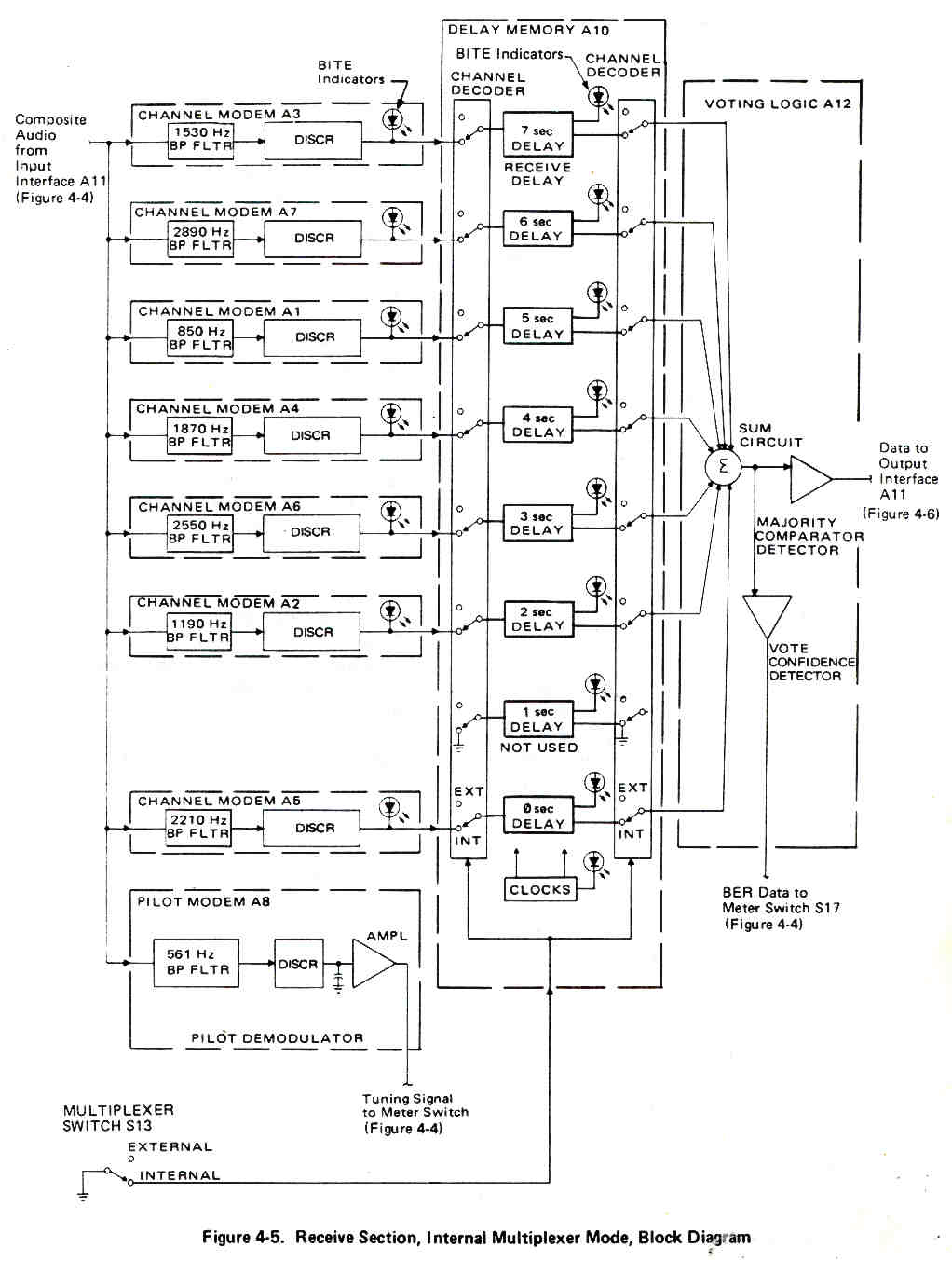
Description: BR Communications, which later merged with TCI to become TCI/BR and was subsequently acquired by Dielectric Inc., produces a series of chirp sounder transmitters and receivers. One notable feature of the Chirp Sounder system is the narrow shift order wire signal that is superimposed on a carrier frequency that sweeps from 2 to typically 30 MHz. This short order wire message has a very high probability of being received globally. BR Communications also developed a line of HF radio modems aimed at achieving a similar high reliability in contact communications. The MD-1142, also known as BR 6029C, operates in two modes, both of which are full duplex (the receiver and transmitter sections are fully independent). In the Internal Multiplexer Mode, a single TTY signal is distributed to seven different channels, with each channel's signal delayed by one second relative to the others. Additionally, a pilot tone at 561.1 Hz is included, enhancing the probability of successful message transmission. In the External Multiplexer Mode, each of the eight channels receives a separate data stream, lacking the redundancy of the Internal Multiplexer Mode. The manual for this device is 0040-6029-15005 and includes details on installation, operation, theory of operation, maintenance, parts breakdown, and schematics. The construction of the device resembles that of the RCS-5A receiver, featuring a motherboard with plug-in daughterboards for each function.
The BR Communications chirp sounder transmitters and receivers are integral components in high-reliability communication systems. The chirp sounder technology employs a unique modulation technique that allows for effective transmission over a wide frequency range, specifically from 2 to 30 MHz. This capability is particularly advantageous in varying atmospheric conditions, where traditional communication methods may falter.
The MD-1142 (BR 6029C) model exemplifies advanced design in HF radio modems. Its full duplex operation means that it can transmit and receive simultaneously, ensuring seamless communication. The Internal Multiplexer Mode is particularly noteworthy, as it enhances message integrity through time-delay multiplexing. By delaying the signals across multiple channels, the system can mitigate the effects of interference and ensure that at least one of the delayed signals is likely to be received correctly.
The pilot tone at 561.1 Hz serves as a reference signal, aiding in the synchronization of the receiver and improving the overall reliability of the communication link. In contrast, the External Multiplexer Mode provides flexibility by allowing each channel to operate independently. This can be beneficial in scenarios where diverse data streams need to be managed without the redundancy provided by the Internal Multiplexer Mode.
The accompanying manual (0040-6029-15005) serves as a comprehensive resource for users, detailing all aspects of the system's operation and maintenance. It includes schematic diagrams that illustrate the internal architecture, enabling technicians to troubleshoot and repair the device effectively. The modular construction, featuring a motherboard with plug-in daughterboards, simplifies upgrades and maintenance, allowing for easy replacement of individual components without the need for extensive rework. Overall, BR Communications' chirp sounder systems and HF radio modems represent a significant advancement in robust communication technology, suitable for various applications requiring reliable and efficient data transmission.BR Communications (later merged with TCI to become TCI/BR, later bought by Dielectric Inc ) makes a line of chirp sounder transmitters and receivers. See my RCS-5 Chirp Sounder page for more on this. One of the features of the Chirp Sounder system is that a narrow shift order wire signal is superimposed on the carrier that is sweeping up in frequ
ency from 2 to typically 30 MHz. This short order wire message has a very high probability of being received anywhere in the world. I think that BR communications developed a line of HF radio modems to try an offer a similar high reliability of contact communications. The MD-1142 aka BR 6029C has two modes of operation both are full fuplex (the receiver and transmitter sections are fully independent), in the Internal Multiplexer Mode a single TTY signal is fed to 7 different channels and the signal in each channel is time delayed by 1 second form all the other channels.
In addition there is a pilot tone at 561. 1 Hz. This mode of operation provides a high probability of getting the message through. In the External Multiplexer Mode each of the 8 channels is fed or receives a separate data stream so it does not have the redundancy of the IMM. In time order the channels are: The manual is 0040-6029-15005 and contains Installation, Operation, Theory of Operation, Maintenance with parts breakdown and schematics.
The construction is similar to the RCS-5A receiver, that is a mother board with plug in daughter baords for each function.
The BR Communications chirp sounder transmitters and receivers are integral components in high-reliability communication systems. The chirp sounder technology employs a unique modulation technique that allows for effective transmission over a wide frequency range, specifically from 2 to 30 MHz. This capability is particularly advantageous in varying atmospheric conditions, where traditional communication methods may falter.
The MD-1142 (BR 6029C) model exemplifies advanced design in HF radio modems. Its full duplex operation means that it can transmit and receive simultaneously, ensuring seamless communication. The Internal Multiplexer Mode is particularly noteworthy, as it enhances message integrity through time-delay multiplexing. By delaying the signals across multiple channels, the system can mitigate the effects of interference and ensure that at least one of the delayed signals is likely to be received correctly.
The pilot tone at 561.1 Hz serves as a reference signal, aiding in the synchronization of the receiver and improving the overall reliability of the communication link. In contrast, the External Multiplexer Mode provides flexibility by allowing each channel to operate independently. This can be beneficial in scenarios where diverse data streams need to be managed without the redundancy provided by the Internal Multiplexer Mode.
The accompanying manual (0040-6029-15005) serves as a comprehensive resource for users, detailing all aspects of the system's operation and maintenance. It includes schematic diagrams that illustrate the internal architecture, enabling technicians to troubleshoot and repair the device effectively. The modular construction, featuring a motherboard with plug-in daughterboards, simplifies upgrades and maintenance, allowing for easy replacement of individual components without the need for extensive rework. Overall, BR Communications' chirp sounder systems and HF radio modems represent a significant advancement in robust communication technology, suitable for various applications requiring reliable and efficient data transmission.BR Communications (later merged with TCI to become TCI/BR, later bought by Dielectric Inc ) makes a line of chirp sounder transmitters and receivers. See my RCS-5 Chirp Sounder page for more on this. One of the features of the Chirp Sounder system is that a narrow shift order wire signal is superimposed on the carrier that is sweeping up in frequ
ency from 2 to typically 30 MHz. This short order wire message has a very high probability of being received anywhere in the world. I think that BR communications developed a line of HF radio modems to try an offer a similar high reliability of contact communications. The MD-1142 aka BR 6029C has two modes of operation both are full fuplex (the receiver and transmitter sections are fully independent), in the Internal Multiplexer Mode a single TTY signal is fed to 7 different channels and the signal in each channel is time delayed by 1 second form all the other channels.
In addition there is a pilot tone at 561. 1 Hz. This mode of operation provides a high probability of getting the message through. In the External Multiplexer Mode each of the 8 channels is fed or receives a separate data stream so it does not have the redundancy of the IMM. In time order the channels are: The manual is 0040-6029-15005 and contains Installation, Operation, Theory of Operation, Maintenance with parts breakdown and schematics.
The construction is similar to the RCS-5A receiver, that is a mother board with plug in daughter baords for each function.
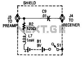
Receiver-Interface Circuit For Preamps Circuit
The purpose of the receiver/interface circuit is to pass RF to the receiver through capacitor C9, while adding DC power to the feedline through resistor R2 and RF choke L7.
The receiver/interface circuit is designed to facilitate the transmission of radio...
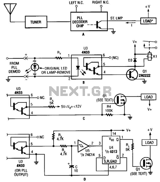
Interfaces For The Remote-Control Transmitter Circuit
Several possible interface circuits are presented for use with a remote-control transmitter. The circuit labeled A demonstrates a typical FM stereo MUX decoder with a load connected directly to the open-collector output of a TA7343 PLL. The circuit labeled B...
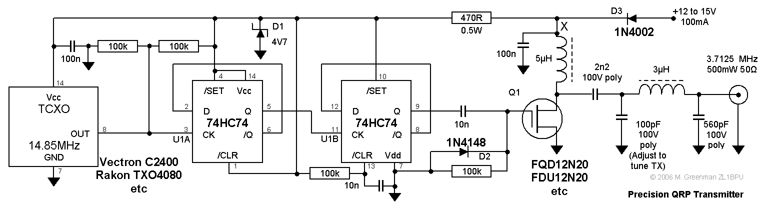
Precision QRP Transmitter
This compact transmitter is suitable for less demanding Doppler propagation measurements. It is designed for operation on the 80m band but can be easily adapted for the 40m or 20m bands. The output power is approximately 500mW of unmodulated carrier,...
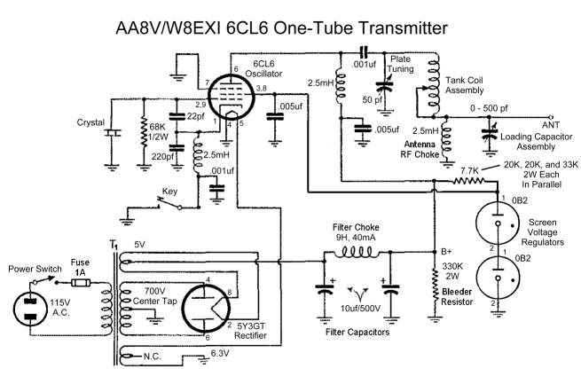
A8V W8EXI 6CL6 One Tube Transmitter
A8V W8EXI 6CL6 One Tube Transmitter. The operation of the 6CL6 transmitter is actually quite sophisticated.
The A8V W8EXI 6CL6 One Tube Transmitter is a compact and efficient radio frequency (RF) transmitter that utilizes a single 6CL6 vacuum tube for its...
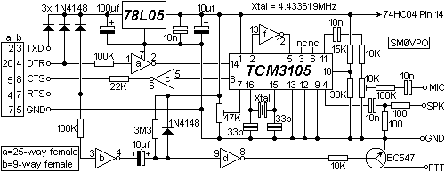
BayComm packet modem
Ensure the correct 9-pin D-type connector is used so that the pins fit properly into the board. The two outer mounting holes for the 9-pin D-type connector should have a diameter of 3mm, while the holes for the pins should...
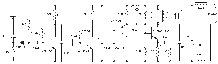
Amazing All-Band Receiver
The Amazing All-Band Receiver is essentially a diode detector followed by a high-gain audio amplifier. This device is not a multi-band receiver; it captures all signals simultaneously. The detector utilizes a biased Schottky diode for superior sensitivity and bandwidth, enabling...
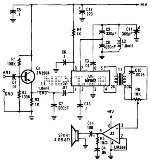
Simple Low-Frequency Receiver
Using an NE602 heterodyne detector and U1 as an RF amplifier, this receiver tunes the middle portion of the low-frequency spectrum from 150 to 250 kHz. U2 is a loudspeaker amplifier.
The described circuit employs an NE602 integrated circuit as...
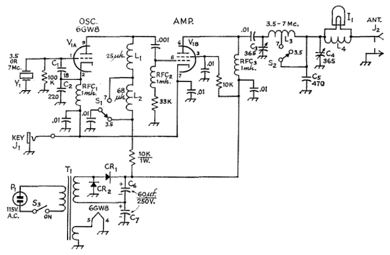
McCoy Mighty Midget Transmitter
The circuit employs a 6GW8 triode-pentode in an oscillator-amplifier configuration that demonstrates an unconventional application of oscillator principles, coupled with a lack of attention to amplifier stability concerns. Consequently, this transmitter should not be replicated or operated without significant modifications...
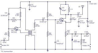
televition transmitter
The camera is oriented to look out the side of the rocket during launch and downward during descent on the parachute. An optional external mirror can be added to enable the camera to look down during lift-off. The transmitter antenna,...