


Music On Hold Box Circuit

Description: The LS3404 melody chip is activated when the hold switch (SI) is pressed, causing SCR1 to conduct and maintain the telephone line through Tl, Rl, and LED1. The voltage across Rl and LED1 is utilized to power the melody chip. Additionally, Q1 and Q2 form a restart circuit to ensure the melody chip remains operational during the hold period.
The LS3404 melody chip is a specialized integrated circuit designed to generate musical tones. Upon pressing the hold switch (SI), an electrical signal is sent to the gate of the silicon-controlled rectifier (SCR1), which then enters the conductive state. This action effectively connects the telephone line to the circuit, allowing the melody chip to function.
Resistor Rl and LED1 are connected in series, forming a voltage divider that provides the necessary operating voltage to the melody chip. The LED1 serves a dual purpose; it not only indicates that the hold function is active but also contributes to the voltage drop across Rl. This voltage is critical for the proper functioning of the LS3404, ensuring that it receives sufficient power to operate.
Transistors Q1 and Q2 are configured to create a restart circuit that maintains the melody chip's operation. When the melody chip is activated, Q1 turns on, allowing current to flow through Q2, which keeps the circuit in a stable state. This configuration prevents the melody chip from shutting down during the hold period, ensuring continuous sound output. The restart circuit is essential for applications where the hold function may be activated for extended durations, as it guarantees that the melody continues to play without interruption.
The overall design allows for a seamless user experience during the hold operation, combining visual feedback through LED1 and auditory feedback through the melody chip, while ensuring reliability through the restart circuit. This arrangement is particularly useful in telephone systems where maintaining communication aesthetics is important. Ul, an LS3404 melody chip is activated when hold SI is pressed, which causes SCR1 to conduct and hold the telephone line via Tl, Rl, and LED1. The voltage across Rl and LED1 is used to activate the melody chip. Ql and Q2 form a restart circuit to keep the melody chip going during hold.
The LS3404 melody chip is a specialized integrated circuit designed to generate musical tones. Upon pressing the hold switch (SI), an electrical signal is sent to the gate of the silicon-controlled rectifier (SCR1), which then enters the conductive state. This action effectively connects the telephone line to the circuit, allowing the melody chip to function.
Resistor Rl and LED1 are connected in series, forming a voltage divider that provides the necessary operating voltage to the melody chip. The LED1 serves a dual purpose; it not only indicates that the hold function is active but also contributes to the voltage drop across Rl. This voltage is critical for the proper functioning of the LS3404, ensuring that it receives sufficient power to operate.
Transistors Q1 and Q2 are configured to create a restart circuit that maintains the melody chip's operation. When the melody chip is activated, Q1 turns on, allowing current to flow through Q2, which keeps the circuit in a stable state. This configuration prevents the melody chip from shutting down during the hold period, ensuring continuous sound output. The restart circuit is essential for applications where the hold function may be activated for extended durations, as it guarantees that the melody continues to play without interruption.
The overall design allows for a seamless user experience during the hold operation, combining visual feedback through LED1 and auditory feedback through the melody chip, while ensuring reliability through the restart circuit. This arrangement is particularly useful in telephone systems where maintaining communication aesthetics is important. Ul, an LS3404 melody chip is activated when hold SI is pressed, which causes SCR1 to conduct and hold the telephone line via Tl, Rl, and LED1. The voltage across Rl and LED1 is used to activate the melody chip. Ql and Q2 form a restart circuit to keep the melody chip going during hold.
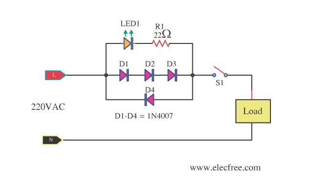
Mains Voltage Indicator with a LED
A need exists for a 220V AC line light display or main voltage monitor due to frequent electrical issues in a home.
To create a 220V AC line light display or voltage monitor, a circuit can be designed using a combination...
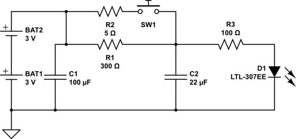
Motion sensing LED Quantum Bits
The circuit operates as follows: The LED is typically powered at a low brightness through resistors R1 and R3. SW1 functions as a spring and wire-based accelerometer. When SW1 is activated, capacitor C2 charges rapidly at a rate determined by...
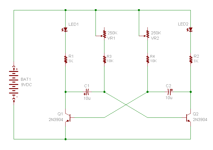
flashing leds kit
This kit includes fully illustrated instructions and a circuit schematic. Components are adequately spaced for easy assembly and value identification on the board. The circuit board features silk-screened outlines for component placement, and the circuit pads on the solder side...
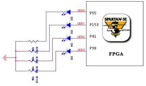
led interfacing with spartan 3e webserver
The Spartan-3E board features four LEDs connected to FPGA I/O pins, as detailed in the accompanying table. Each LED's cathode is connected to ground through a 330-ohm resistor. To illuminate a specific LED, the corresponding FPGA control signal must be...
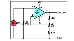
using led as a light sensor
This circuit demonstrates the utilization of a standard LED as a light sensor. It leverages the photovoltaic voltage generated across the LED when exposed to light.
The circuit operates on the principle that an LED can function as a photodiode, generating...
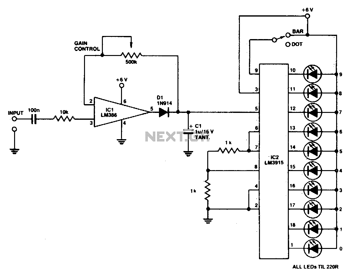
Led bar-dot level meter
A simple power meter can be configured to provide a bar or dot display for a hi-fi system. Green LEDs are used for levels 0 to 7, yellow for level 8, and red for levels 9 to indicate peak power....
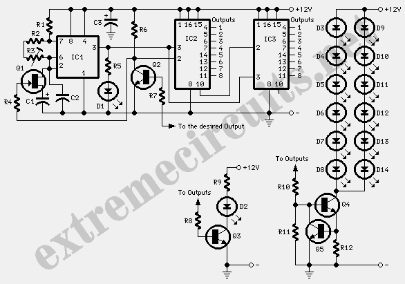
Bar-Mode Lights Sequencer
The terminal of R7, indicated by an arrow, must be connected to the desired output pin of IC2 or IC3 to select the number of LEDs or clusters that will form the bar. For instance, to drive seven LEDs or...
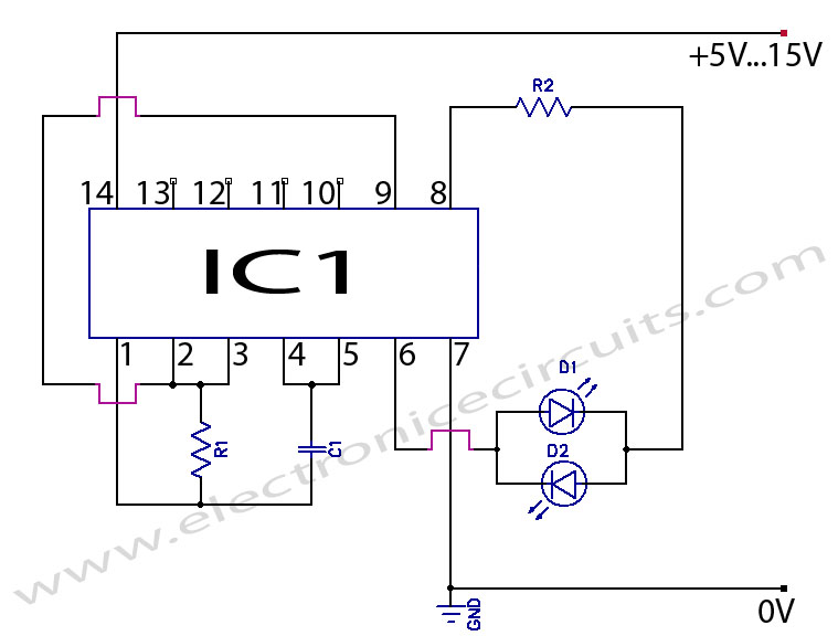
2 LED CMOS Flasher
Two LED CMOS Flasher Circuit Diagram. This is a simple two LED CMOS robot (flasher, multivibrator) circuit using CD4069 six inverters.
The two LED CMOS flasher circuit utilizes the CD4069 integrated circuit, which contains six inverters, to create a multivibrator configuration....
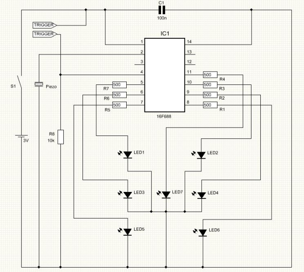
Shaking electronic LED Dice
I've always wanted to build an electronic LED dice, but something different from what we see on the internet. Making it motion controlled... now that's new! Many new cell phones that have accelerometers built in also have dice games. These...