


MUSICAL TELEPHONE RINGER
#telephone
#ringer
#melody-synthesizer
#ring detector
#relay
#signal rectification
#audio
#communication
#electronics
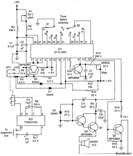
Description: The core component of the circuit is IC1, the AY-3-1350 melody synthesizer IC from General Instrument. IC2 is a TCM1512 telephone ring detector IC powered by the telephone line. The circuit operates when IC2 detects a ring pulse on the telephone line. The detector rectifies the ring signal internally and outputs a voltage to relay RY1, a single-pole single-throw (SPST) reed-type relay with 5-volt contacts, causing its contacts to close. This action pulls pin 12 (the ON/OFF control) of IC1 low (logic 0), prompting it to output a signal—the selected tune—to the transistor amplifier Q2. The amplified signal is then sent to the speaker. The melody continues to play until the tune is finished, at which point IC1 reverts to standby mode, or until the phone is taken off the hook. Lifting the handset interrupts the ring pulses to IC2, which opens RY1. When the relay contacts open, pin 12 of IC1 goes high, returning the circuit to standby mode, ready for the next incoming phone call.
The circuit design centers around two integrated circuits: the AY-3-1350 and the TCM1512, each serving distinct functions essential for melody playback upon incoming phone calls. The AY-3-1350 is a dedicated melody synthesizer capable of generating various tunes through pre-defined sound patterns. It is controlled by an external voltage signal, which in this case is provided by the relay operation initiated by the TCM1512.
The TCM1512 operates by detecting the AC ring signal typically present on telephone lines. This IC is designed to recognize the specific frequency and voltage levels associated with ringing. Upon detection, it converts the AC signal into a usable DC voltage, which activates the relay RY1. The use of an SPST reed relay allows for minimal power consumption and quick switching, making it suitable for low-voltage applications like this circuit.
When the relay closes, it creates a path that pulls down the control pin of the AY-3-1350, enabling the melody generation. The output from IC1 is then amplified by transistor Q2, ensuring that the sound is sufficiently loud when played through the speaker. The circuit is designed to seamlessly transition between active and standby modes, effectively managing power consumption and ensuring that the melody only plays in response to incoming calls.
The operation concludes when the melody finishes or when the phone is lifted off the hook. Lifting the handset interrupts the ring signal, causing the relay to open and the AY-3-1350 to return to its standby state. This design not only provides an auditory alert for incoming calls but does so with efficiency and responsiveness, making it an effective solution for enhancing traditional telephone systems.The heart of the circuit is IC1, General Instrument`s AY-3-1350 melody-synthesizer IC. IC2 is a TCM1512 telephone ring detector IC that is powered by the telephone line. The circuit`s operation begins when IC2 senses a ring pulse on the telephone line. The detector (internally) rectifies the ring signal and then outputs a voltage to relay RY1 (an SPST reed-type relay with 5 volt contacts), causing its contacts to close. That pulls pin 12 (the ON/OFF control) of IC1 low (logic 0 ), causing it to output a signal-the selected tune-to transistor amplifier Q2. The amplified signal is then fed to the speaker. The melody continues to play either until the tune is finished (at which time IC1 returns to the standby mode), or until someone takes the phone off the hook.
Taking the phone off the hook dis-continues the ring pulses to IC2, which opens RY1. When the relay contacts open, pin 12 of IC1 goes high, returning the circuit to the standby mode to wait for the next incoming phone call.
The circuit design centers around two integrated circuits: the AY-3-1350 and the TCM1512, each serving distinct functions essential for melody playback upon incoming phone calls. The AY-3-1350 is a dedicated melody synthesizer capable of generating various tunes through pre-defined sound patterns. It is controlled by an external voltage signal, which in this case is provided by the relay operation initiated by the TCM1512.
The TCM1512 operates by detecting the AC ring signal typically present on telephone lines. This IC is designed to recognize the specific frequency and voltage levels associated with ringing. Upon detection, it converts the AC signal into a usable DC voltage, which activates the relay RY1. The use of an SPST reed relay allows for minimal power consumption and quick switching, making it suitable for low-voltage applications like this circuit.
When the relay closes, it creates a path that pulls down the control pin of the AY-3-1350, enabling the melody generation. The output from IC1 is then amplified by transistor Q2, ensuring that the sound is sufficiently loud when played through the speaker. The circuit is designed to seamlessly transition between active and standby modes, effectively managing power consumption and ensuring that the melody only plays in response to incoming calls.
The operation concludes when the melody finishes or when the phone is lifted off the hook. Lifting the handset interrupts the ring signal, causing the relay to open and the AY-3-1350 to return to its standby state. This design not only provides an auditory alert for incoming calls but does so with efficiency and responsiveness, making it an effective solution for enhancing traditional telephone systems.The heart of the circuit is IC1, General Instrument`s AY-3-1350 melody-synthesizer IC. IC2 is a TCM1512 telephone ring detector IC that is powered by the telephone line. The circuit`s operation begins when IC2 senses a ring pulse on the telephone line. The detector (internally) rectifies the ring signal and then outputs a voltage to relay RY1 (an SPST reed-type relay with 5 volt contacts), causing its contacts to close. That pulls pin 12 (the ON/OFF control) of IC1 low (logic 0 ), causing it to output a signal-the selected tune-to transistor amplifier Q2. The amplified signal is then fed to the speaker. The melody continues to play either until the tune is finished (at which time IC1 returns to the standby mode), or until someone takes the phone off the hook.
Taking the phone off the hook dis-continues the ring pulses to IC2, which opens RY1. When the relay contacts open, pin 12 of IC1 goes high, returning the circuit to the standby mode to wait for the next incoming phone call.
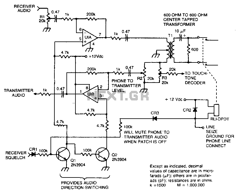
Autopatch telephone line interface
This circuit facilitates the communication link between the receiver and the phone line, as well as the phone line and the transmitter, utilizing an operational amplifier (op-amp) for signal amplification.
The described circuit connects a receiver to a phone line and...
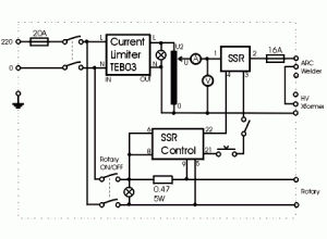
Power Control Unit
This shows the overall circuit diagram of the power control unit. On the left, there is a main relay controlled by the key switch.
The power control unit circuit diagram illustrates the fundamental components and their interconnections, providing a clear overview...
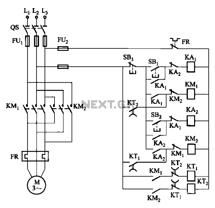
Four reversing operation of the reverse brake circuit
The circuit depicted in Figure 3-131 utilizes a relay instead of a speed control relay. It is designed to operate effectively in dusty environments and other challenging conditions.
The circuit operates by employing a relay as a primary switching mechanism, which...
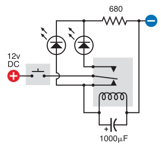
relay circuit
The intended result is for the relay to oscillate and the LEDs to flash when the button is pressed. However, when the button is pressed, the leftmost LED lights constantly, and nothing else happens. There is voltage across the left...
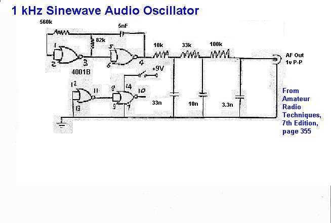
1 KHz Audio Oscillator schematic
This circuit consists of a CMOS square wave oscillator on a frequency of approximately 1 kHz. The RC filter, which has a roll-off frequency of 500 Hz, filters the harmonics, providing a sine-wave output.
The described circuit features a CMOS...
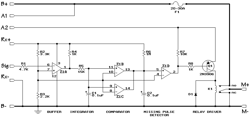
R/C On/Off Motor Controller with Brake
A relay-based on/off controller on the other hand can be very efficient. A typical relay has a contact resistance of 3 milliOhm. At 20A, this translates to a voltage drop of 0.06 volts, with a power loss of 1.2W. The...
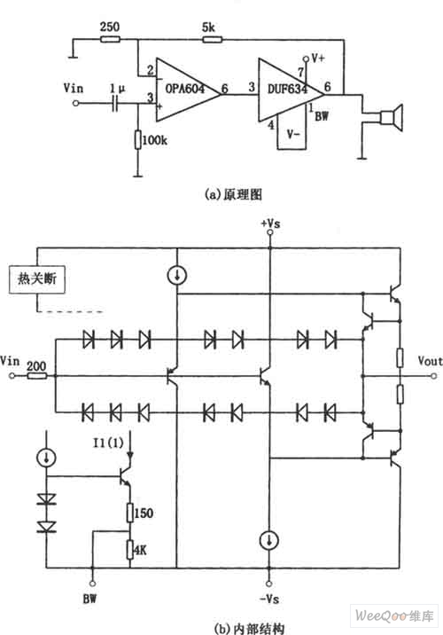
OPA604 High Performance and Small Power Audio Amplifier
The provided image depicts a high-performance and low-power audio power amplifier circuit. The initial stage utilizes the MOSFET hi-fi operational amplifier OPA604, while the subsequent stage employs the high-speed buffer BUF634. Voltage series negative feedback is implemented between the two...
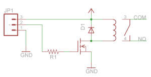
Relay Circuit and Breakout Board
Before proceeding with the toaster oven reflow oven project, it is essential to understand the operation of relays and how to construct a simple relay breakout board. This discussion will focus on the design of a relay breakout board specifically...
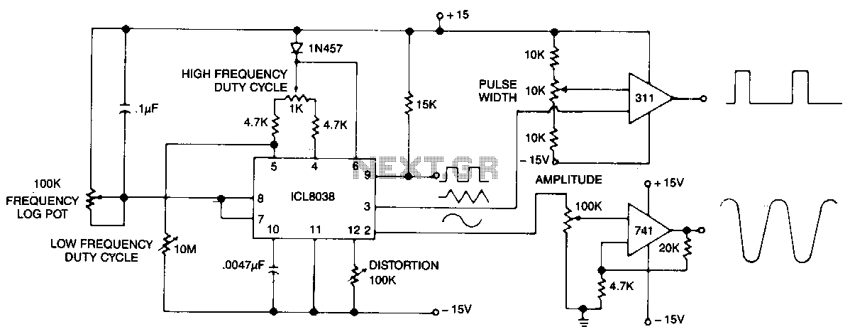
Precision-audio-waveform-generator
This circuit generates sinusoidal, square, and triangle waveforms simultaneously. The frequency can be set to a specific value or varied as indicated. An operational amplifier can be added for enhanced drive capability and simplified amplitude adjustment. Additionally, a simple comparator...