


Phone Bill Calculator
#phone
#ringing signal
#rectifier
#capacitor
#variable resistor
#logic high
#telecommunication
#phone line
#DC blocking
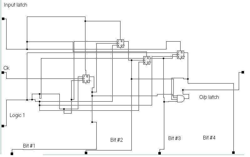
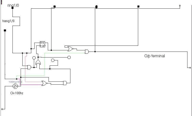
Description: This circuit is used to give "1" signal when the phone is ringing. As you can see the ct. is directly connected to the phone line. The 4.7 uF blocks the DC loading on the phone line. This means that there is voltage on the 10K resistance only when the phone is ringing. This voltage is of course alternating, and it is half wave rectified by the diode, so that, only the positive spikes charge the capacitor. So the net result is that the capacitor is charged only when the phone line is ringing. The variable resistor is used to absorb the "silence" period during the ringing so that the voltage stays at logic high. By adjusting this variable resistance, you can prolong or shorten the time period after which the capacitor voltage will turn to logic low. This period should be adjusted to be about 4 seconds. In fact, is not important and can be entirely omitted from the circuit, it is simply a 4 bit counter that its clear is used to give "1" signal from the anding of the " 4 "o/p bits, but it's importance rises when the ck used is very slow that's when ring 1/0 gives "1" signal, this latch "1" gives instantaneous "1" signal which exhibits "1" signal at o/p , that's we donut have to wait for the ck to get "1" signal from latch 2. 1-Prevent "1" signal at o/p when there is a coming call. 2-Making o/p signal when I make a call. This is done using a delay flip-flop, and a logic ct. which controls two things, the o/p signal and the ck of the delay flip-flop, as in the design, when phone rings, ring1/0 gives "1" signal, so "D" pin now have "1" signal on it before raising the hang, ring1/0 gives "1" signal, and also hang 1/0 gives 0 SIGNAL. After raising the hang to answer the phone, we have: "1" signal from ring1/0 as the capacitor has not yet discharged, and "1" signal from hang1/0 after we raised the hang, so this means that is the ck is enabled on the delay f.f, but when the capacitor discharges, ring1/0 gives now "0" signal, this means that the expected thing here is to have o/p signal as the hang is still raised, but the design exhibits the ck at this instance on the delay f.f, making its "q" pin high as long as the hang is raised, when the call is finished and the hang is off, this enables the ck and we go back to square one having "0" signals out of both ring1/0 and hang 1/0, and so waiting for any further signals.
The circuit operates by detecting the ringing signal from a telephone line, which is an alternating current (AC) signal. The connection to the phone line is established through a current transformer (CT), which isolates the circuit from direct DC loading. A capacitor of 4.7 µF is used to block DC voltage, allowing only the AC ringing signal to pass through. This signal generates a voltage across a 10 kΩ resistor, which is present only during the ringing period.
The AC signal is then half-wave rectified using a diode, allowing only the positive half-cycles to charge the capacitor. This charging process ensures that the capacitor accumulates voltage only when the phone is ringing, enabling the circuit to output a logic high signal. The variable resistor in the circuit serves to extend the duration of the output signal during the "silence" periods of the ringing, effectively holding the capacitor's voltage at a logic high for a predetermined time, adjustable to approximately four seconds.
Additionally, a 4-bit counter is incorporated into the design to provide a secondary function, although it is not critical for basic operation. This counter can prevent the output signal from being activated when a call is incoming. The design includes a delay flip-flop that is controlled by the ringing signal and a hang signal, which indicates whether the phone is off the hook.
When the phone rings, the output from the ringing detection circuit (ring1/0) provides a logic high signal, which is fed to the D input of the delay flip-flop. Once the phone is answered (hang signal goes high), both the ring1/0 and hang1/0 signals are high, enabling the clock input of the flip-flop. As the capacitor discharges after the ringing stops, the ring1/0 signal transitions to low, but the design ensures that the output remains high as long as the hang signal is active. When the call is completed and the hang signal goes low, the circuit resets, and both ring1/0 and hang1/0 signals return to low, preparing the circuit for subsequent calls.
This circuit design effectively manages the output signaling during ringing and call states, ensuring reliable operation without unnecessary delays or false triggers. This circuit is used to give "1" signal when the phone is ringing. As you can see the ct. is directly connected to the phone line. The 4.7 uF blocks the DC loading on the phone line. This means that there is voltage on the 10K resistance only when the phone is ringing. This voltage is of course alternating, and it is half wave rectified by the diode, so that, only the positive spikes charge the capacitor. So the net result is that the capacitor is charged only when the phone line is ringing. The variable resistor is used to absorb the "silence" period during the ringing so that the voltage stays at logic high.
By adjusting this variable resistance, you can prolong or shorten the time period after which the capacitor voltage will turn to logic low. This period should be adjusted to be about 4 seconds. In fact, is not important and can be entirely omitted from the circuit, it is simply a 4 bit counter that its clear is used to give "1" signal from the anding of the " 4 "o/p bits, but it's importance rises when the ck used is very slow that's when ring 1/0 gives "1" signal, this latch "1" gives instantaneous "1" signal which exhibits "1" signal at o/p , that's we donut have to wait for the ck to get "1" signal from latch 2. 1-Prevent "1" signal at o/p when there is a coming call. 2-Making o/p signal when I make a call. This is done using a delay flip-flop ,and a logic ct. which controls two things, the o/p signal and the ck of the delay flip-flop, as in the design , when phone rings ,ring1/0 gives "1" signal, so "D" pin now have "1" signal on it before raising the hang, ring1/0 gives "1" signal, and also hang 1/0 gives 0 SIGNAL.
After raising the hang to answer the phone ,we have : "1" signal from ring1/0 as the capacitor has not yet discharged, and "1" signal from hang1/0 after we raised the hang, so this means that is the ck is enabled on the delay f.f , but when the capacitor discharges, ring1/0 gives now "0" signal ,this means that the expected thing here is to have o/p signal as the hang is still raised , but the design exhibits the ck at this instance on the delay f.f , making its "q" pin high as long as the hang is raised ,when the call is finished and the hang is off, this enables the ck and we go back to square one having"0" signals out of both ring1/0 and hang 1/0,and so waiting for any further signals.
The circuit operates by detecting the ringing signal from a telephone line, which is an alternating current (AC) signal. The connection to the phone line is established through a current transformer (CT), which isolates the circuit from direct DC loading. A capacitor of 4.7 µF is used to block DC voltage, allowing only the AC ringing signal to pass through. This signal generates a voltage across a 10 kΩ resistor, which is present only during the ringing period.
The AC signal is then half-wave rectified using a diode, allowing only the positive half-cycles to charge the capacitor. This charging process ensures that the capacitor accumulates voltage only when the phone is ringing, enabling the circuit to output a logic high signal. The variable resistor in the circuit serves to extend the duration of the output signal during the "silence" periods of the ringing, effectively holding the capacitor's voltage at a logic high for a predetermined time, adjustable to approximately four seconds.
Additionally, a 4-bit counter is incorporated into the design to provide a secondary function, although it is not critical for basic operation. This counter can prevent the output signal from being activated when a call is incoming. The design includes a delay flip-flop that is controlled by the ringing signal and a hang signal, which indicates whether the phone is off the hook.
When the phone rings, the output from the ringing detection circuit (ring1/0) provides a logic high signal, which is fed to the D input of the delay flip-flop. Once the phone is answered (hang signal goes high), both the ring1/0 and hang1/0 signals are high, enabling the clock input of the flip-flop. As the capacitor discharges after the ringing stops, the ring1/0 signal transitions to low, but the design ensures that the output remains high as long as the hang signal is active. When the call is completed and the hang signal goes low, the circuit resets, and both ring1/0 and hang1/0 signals return to low, preparing the circuit for subsequent calls.
This circuit design effectively manages the output signaling during ringing and call states, ensuring reliable operation without unnecessary delays or false triggers. This circuit is used to give "1" signal when the phone is ringing. As you can see the ct. is directly connected to the phone line. The 4.7 uF blocks the DC loading on the phone line. This means that there is voltage on the 10K resistance only when the phone is ringing. This voltage is of course alternating, and it is half wave rectified by the diode, so that, only the positive spikes charge the capacitor. So the net result is that the capacitor is charged only when the phone line is ringing. The variable resistor is used to absorb the "silence" period during the ringing so that the voltage stays at logic high.
By adjusting this variable resistance, you can prolong or shorten the time period after which the capacitor voltage will turn to logic low. This period should be adjusted to be about 4 seconds. In fact, is not important and can be entirely omitted from the circuit, it is simply a 4 bit counter that its clear is used to give "1" signal from the anding of the " 4 "o/p bits, but it's importance rises when the ck used is very slow that's when ring 1/0 gives "1" signal, this latch "1" gives instantaneous "1" signal which exhibits "1" signal at o/p , that's we donut have to wait for the ck to get "1" signal from latch 2. 1-Prevent "1" signal at o/p when there is a coming call. 2-Making o/p signal when I make a call. This is done using a delay flip-flop ,and a logic ct. which controls two things, the o/p signal and the ck of the delay flip-flop, as in the design , when phone rings ,ring1/0 gives "1" signal, so "D" pin now have "1" signal on it before raising the hang, ring1/0 gives "1" signal, and also hang 1/0 gives 0 SIGNAL.
After raising the hang to answer the phone ,we have : "1" signal from ring1/0 as the capacitor has not yet discharged, and "1" signal from hang1/0 after we raised the hang, so this means that is the ck is enabled on the delay f.f , but when the capacitor discharges, ring1/0 gives now "0" signal ,this means that the expected thing here is to have o/p signal as the hang is still raised , but the design exhibits the ck at this instance on the delay f.f , making its "q" pin high as long as the hang is raised ,when the call is finished and the hang is off, this enables the ck and we go back to square one having"0" signals out of both ring1/0 and hang 1/0,and so waiting for any further signals.
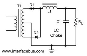
Full-Wave Rectifier circuit
A circuit that utilizes both positive and negative alternations in an alternating current to generate direct current. There are two types of full-wave rectifier circuits: one that employs two diodes and requires a center-tapped transformer, and another that uses four...
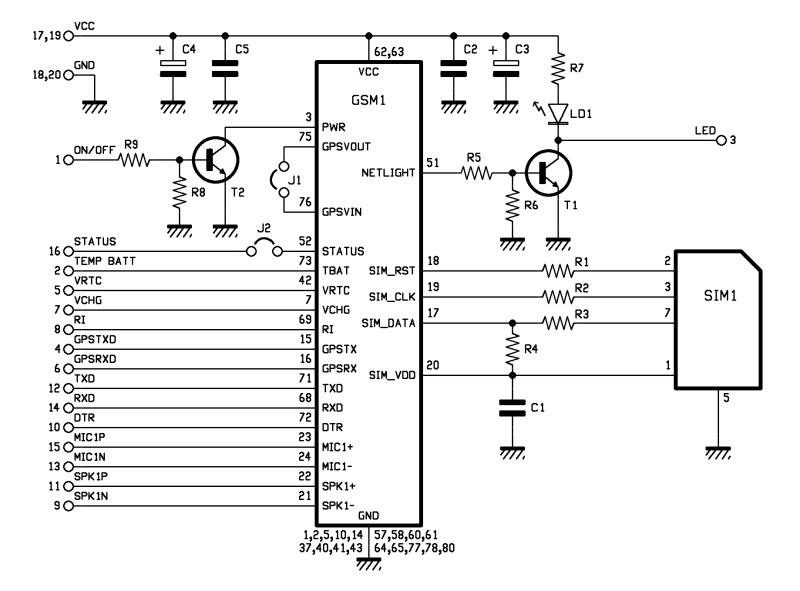
Help me Understand this Circuit Schematic
The roles of capacitors C1, C4, and C5 in a circuit may not be immediately clear. Capacitors on the power rail help to smooth out the signal by reducing current ripple, which can be observed using an oscilloscope. Resistors R6...
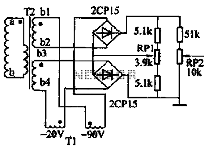
Single-phase full-wave rectifier circuit 02 phase
The closed-loop system consists of longitudinal and transverse components. The circuit operates as follows: a control circuit from the stepping motor CNC system issues a command, which the receiver detects. This signal is processed through a phase-sensitive rectifier to convert...
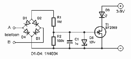
Phone Busy Indicator schematic
This indicator shows whether the phone is busy or not. When the line is busy, LED D6 is off. The line voltage at points A and B is attached. By the rectifier bridge behind the connection, the polarity does not...
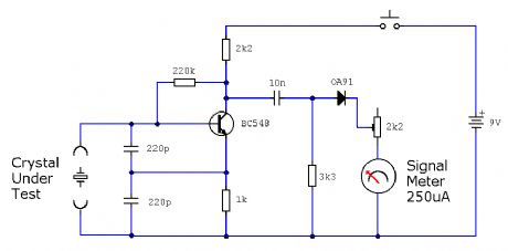
ELF MONITOR
The capacitor instrument is not intended for measuring the capacitance of capacitors; rather, it is designed to identify whether a capacitor is functional or defective, as well as to detect short circuits or open circuits. This functionality provides reliable quality...
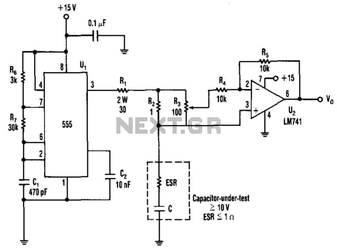
Capacitor Esr Measurer
The equivalent series resistance (ESR) of a capacitor can be measured using this circuit and an AC voltmeter. It functions as a 50-kHz square-wave generator, driving a current waveform of approximately ±180 mA through the capacitor-under-test via resistors R1 and...
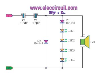
Detect ringing signal tone with light and sound
The circuit detects a ringing signal tone and provides both light and sound indicators. It is user-friendly and of good quality, and it does not require a power supply to operate, functioning solely to detect the ringing signal.
The described circuit...
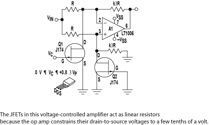
Circuit Detects Phone-Line Breaks
Alarm system designs often require circuitry that can detect whether a phone line is active or broken. The primary challenge in this design is to draw less than 5 µA from the phone line, which operates within a voltage range...
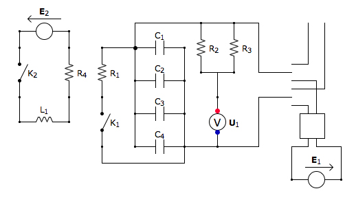
Capacitor Box Circuit
This is the discharging circuit. The red lines indicate the flow of energy from the capacitors to the terminals when the switch is in the upward position. The circuit is complete due to the connection of the terminals by Ni-Chrome...