


Phone Line In use LED with 2N2222
#phone line
#LED indicator
#2N2222
#FET
#voltage drop
#off hook
#tip and ring
#blinking LED
#telecommunication
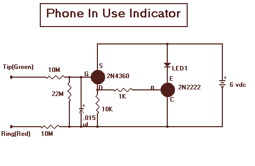
Description: With this circuit mounted in or near every phone in the house, it will allow users to know if the phone is being used and not to pick up the phone. When a phone is taken off hook, the voltage across the tip and ring terminals drops to 10 volts or less. This will cause the FET (2N4360) to turn on and also turn on the transistor (2N2222). When the transistor turns on it will allow current to flow through the LED and make it light. A blinking LED could be used to make the effect better.
This circuit serves as a phone usage indicator, providing a visual cue when a phone is off-hook. The design utilizes a field-effect transistor (FET) and a bipolar junction transistor (BJT) to detect the change in voltage across the phone's tip and ring terminals.
The FET (2N4360) is chosen for its high input impedance, allowing it to sense the voltage drop without significantly affecting the phone's operation. When the phone is off-hook, the voltage at the tip and ring terminals falls below 10 volts, which activates the FET. This activation leads to the conduction of current through the FET, which subsequently triggers the BJT (2N2222).
The BJT is configured in a common-emitter arrangement, where its base is connected to the FET's drain. Once the BJT turns on, it allows a larger current to flow from the collector to the emitter, powering the LED. The LED serves as the visual indicator, illuminating to signal that the phone is in use.
For enhanced visibility, a blinking LED can be incorporated by adding a simple timer circuit or using a 555 timer IC in astable mode. This modification would create a pulsing effect, making the indicator more noticeable.
Overall, this circuit provides a straightforward and effective solution for indicating phone usage, utilizing common electronic components that are readily available. Proper attention to component ratings and connections is essential to ensure reliable operation within the household environment.With this circuit mounted in or near every phone in the house, it will allow users to know if the phone is being used and not to pick up the phone. When a phone is taken off hook, the voltage across the tip and ring terminals drops to 10 volts or less.
This will cause the FET (2N4360) to turn on and also turn on the transistor (2N2222). When the transistor turns on it will allow current to flow through the LED and make it light. A blinking LED could be used to make the effect better.
This circuit serves as a phone usage indicator, providing a visual cue when a phone is off-hook. The design utilizes a field-effect transistor (FET) and a bipolar junction transistor (BJT) to detect the change in voltage across the phone's tip and ring terminals.
The FET (2N4360) is chosen for its high input impedance, allowing it to sense the voltage drop without significantly affecting the phone's operation. When the phone is off-hook, the voltage at the tip and ring terminals falls below 10 volts, which activates the FET. This activation leads to the conduction of current through the FET, which subsequently triggers the BJT (2N2222).
The BJT is configured in a common-emitter arrangement, where its base is connected to the FET's drain. Once the BJT turns on, it allows a larger current to flow from the collector to the emitter, powering the LED. The LED serves as the visual indicator, illuminating to signal that the phone is in use.
For enhanced visibility, a blinking LED can be incorporated by adding a simple timer circuit or using a 555 timer IC in astable mode. This modification would create a pulsing effect, making the indicator more noticeable.
Overall, this circuit provides a straightforward and effective solution for indicating phone usage, utilizing common electronic components that are readily available. Proper attention to component ratings and connections is essential to ensure reliable operation within the household environment.With this circuit mounted in or near every phone in the house, it will allow users to know if the phone is being used and not to pick up the phone. When a phone is taken off hook, the voltage across the tip and ring terminals drops to 10 volts or less.
This will cause the FET (2N4360) to turn on and also turn on the transistor (2N2222). When the transistor turns on it will allow current to flow through the LED and make it light. A blinking LED could be used to make the effect better.
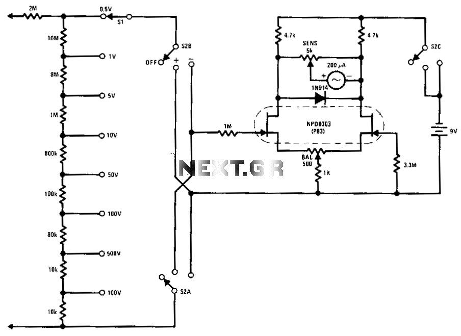
Fet-voltmeter
This FETVM replaces the function of the VTVM and eliminates the need for a standard line cord. Additionally, FET drift rates are significantly better than those of vacuum tube circuits, enabling a full-scale range of 0.5 V, which is not...

FET applications
The Field Effect Transistor (FET) features a very high input impedance, approximately 100 Megaohms for Junction FETs (JFETs) and between 10^4 to 10^9 Megaohms for Metal-Oxide-Semiconductor FETs (MOSFETs). This characteristic effectively eliminates the major limitations of conventional transistors, which typically...
fet small signal analysis
A platform for sharing and discovering articles and documents. Users can upload their knowledge, share it with others, or search through the database to find relevant articles.
This platform serves as a collaborative space where individuals can contribute their expertise in...
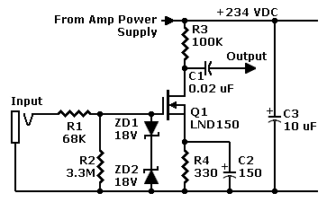
FET Preamp with LND150
The saturation region begins at the knees on the left side. This analysis focuses on curves for negative gate voltages, indicating depletion mode operation. It is important to note that the device can also function in enhancement mode with positive...
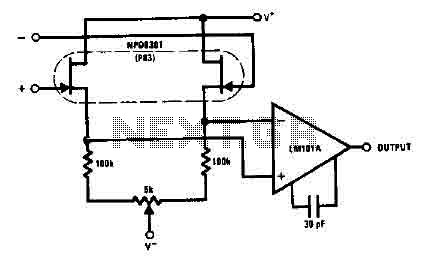
Fet amplifier with NPD8301
The NPD8301 exhibits excellent characteristics across its range of bias current, enhancing common mode rejection. The monolithic double NPD8301 provides an ideal low offset buffer function and features the LM10lA low drift operational amplifier.
The NPD8301 is a monolithic double operational...
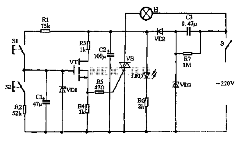
Touch-type FET stepless dimmer
Capacitors C2 and C3, diodes VD2 and VD3, along with other components, form a simple capacitive half-wave rectifier buck power supply. The entire supply control circuit is managed by a switch (S), which can either be a standard small toggle...
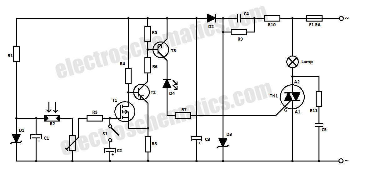
Halogen Light Switch Circuit
This halogen switch circuit utilizes a FET transistor, as the current is influenced by the gate voltage of the FET. The maximum gate voltage is 12V, making the circuit suitable for 12-volt lamps. The resistor R1 has a value of...
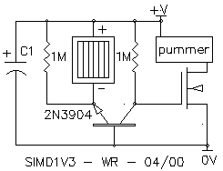
Wilf Rigter`s SIMD1 V3
The SIMD1 V3 is very similar to the NPN flavor of SIMD1 V2, but with the addition of a FET on the output line. This makes life easier for its attached load (since there's no need here for something that...
Circuit Detects Phone-Line Breaks
Alarm system designs often require circuitry that can detect whether a phone line is active or broken. The primary challenge in this design is to draw less than 5 µA from the phone line, which operates within a voltage range...