


Telemetering Beacon For VUSAT
#telemetering
#Morse code
#ham radio
#beacon
#VUSAT
#low cost
#KISS concept
#data transmission
#radio operator
Description: The beacon controller is designed to telemeter data from the VUSAT in Morse code, allowing ham radio operators to decode the information without requiring expensive or complex equipment. The design adheres to the KISS (Keep It Simple, Stupid) principle, utilizing low-cost and readily available components throughout. The controller can accept 16 single-ended data channels, with each channel's DC level representing a parameter to be telemetered. These channels are selected one at a time using two CD4051 analog multiplexers. The voltage from the selected channel is sent to an ADC chip for conversion into its digital equivalent. A 4-bit binary counter manages the channel selection, counting each clock pulse to provide a binary output that serves as the address for the multiplexer. The channel select clock is derived from the End of Message (EOM) signal. The ADC used is the AD7574, an 8-bit Successive Approximation type ADC from Analog Devices. The conversion process begins when the RD! signal goes low, with the digital output becoming available approximately 15 microseconds later. The ADC's 8-bit binary output is routed to the address lines of an EPROM, which stores Morse code data in a lookup table format. The EPROM has two tables: the first table contains 256 rows for Morse-coded messages, while the second table has 16 rows for channel numbers/names. Each row is addressed using 8-bit binary numbers, encoding Morse code with specific bit patterns. A CD4060 IC functions as a 6-bit binary counter and integrated oscillator, counting from 0 to 63, with the oscillator's period set to correspond with the dot duration in Morse code. The output from this counter provides the least significant 6 bits of the address for the EPROM. The EPROM's seventh address bit selects between the two tables, allowing for the transmission of either Morse-coded messages or channel identifiers.
The beacon controller circuit is structured to maximize efficiency and simplicity, ensuring reliable telemetering of data. The two CD4051 analog multiplexers are configured to handle the selection of 16 data channels, allowing for seamless transitions between different parameters. The 4-bit binary counter, typically implemented using a CD4017 or similar IC, ensures that each channel is selected in a systematic manner, driven by clock pulses that synchronize with the EOM signal.
The AD7574 ADC is a critical component, providing accurate conversion of analog signals to digital format. Its design allows for rapid conversion, which is essential for real-time data transmission. The RD! signal, which triggers the conversion process, is derived from the EOM signal, ensuring that data is only processed when a complete message has been transmitted.
The EPROM serves as a storage medium for Morse code data, structured into two distinct tables. The first table, with 256 entries, encodes various Morse messages, while the second table, with 16 entries, corresponds to channel identifiers. The encoding scheme uses binary representations for Morse code, where a dot and a dash are defined by specific bit patterns. For example, a dash is represented as 1110, while a dot is represented as 10. This encoding allows for efficient storage and retrieval of Morse code messages.
The CD4060 counter and oscillator work in tandem to generate the timing signals necessary for Morse code transmission. The oscillator's frequency is carefully chosen to ensure that the timing aligns with the standard Morse code timing conventions. The output from the counter provides the necessary address lines for the EPROM, facilitating the selection of the appropriate Morse code message or channel identifier based on the current operational state of the beacon controller.
In summary, the beacon controller is a well-structured system that effectively utilizes low-cost components to achieve its telemetering objectives. The careful design considerations ensure that ham radio operators can easily decode the transmitted Morse code without the need for complex equipment, adhering to the principles of simplicity and accessibility in electronic design.The beacon controller is intended to be operated for telemetering data available on board of the VUSAT in Morse code so that the ham radio operator can decode the info without any costly and complex equipment. The design strictly follows the KISS concept. It uses low cost, easily available components through out the design. A block diagram of the beacon controller is as shown: The controller can accept 16 single ended data channels of which the dc level represents the parameter to be telemetered. These channels are selected one by one (multiplexed) by using 2 number of CD 4051 (analog MUX). Voltage from selected channel is given to the ADC chip for converting this voltage to its digital equivalent.
A channel counter (4-bit binary counter) controls the channel selection. This counter counts every clock pulse given to it and thus gives a 4 bit binary output. This binary is given to the analog mux as address of the channel to be selected. For every clock pulse to the counter, successive channels are selected. The channel select clock is derived from the end of message signal (EOM), which will be explained later. ADC chip used is AD7574. This chip is an eight bit Successive Approximation type ADC made by `Analog Devices`. This ADC starts converting the analogue voltage input when the RD! signal goes low and the digital value is available at the output pins approximately 15 microseconds later.
RD! signal is derived from the "EOM" signal available from the EPROM. Eight-bit Binary output from ADC is given as the address of 8 most significant bits of the EPROM through two nos. of quad 2 input multiplexer chips. This two chips form an 8 bit 2 input multiplexer, one input is being the 8 bit binary from ADC and the other being the channel address (4 LSBs the upper nibble are made LOW).
This digital MUX selects either the value of the input channel (binary from ADC) or the channel number (4 bit address from channel counter). The selection is also controlled by the control logic that derives the control from the EOM signal from EPROM.
EPROM with 8-bit output stores the Morse code data in look up table form. Only one bit output is used to generate the Morse code and one more bit is used to generate EOM. The memory cell inside the EPROM is divided into two tables. The first table is the "Channel value " table that has 256 rows. Each row represents a message in Morse coded with binary bits. Each row is addressed by using 8 bit binary numbers. A key up condition is coded as `0` and key down as `1`. One can encode Morse code like this and a dash can now be represented as 1110 and a dot can represent as 10 where as a letter space as 000. For example the first entry in this table represents the number "zero zero zero" and to be coded as "111011101110111011100" Similarly table 2 contains a 16 rows, each row represents the channel number/ name encoded with bits as explained above.
If we want to transmit the Morse code for an input channel number/name, then table 2 is selected and the channel address from 7493 is given as the address for table 2 to select the wanted row of messages. Now the string of bits from this row is to be given out one by one sequentially. The counter IC CD4060 does this. This IC contains a multistage counter and an integrated oscillator. This counter is used as a 6 bit binary counter (counts from 0 to 63). The oscillator time period is selected is equal to the dot period (about 120 HZ). So when this counter is enabled, it starts from its reset state of 000000 and counts upwards until it is reset.
This Morse counter output form the least 6 bits of address to the EPROM. Seventh address bit of the EPROM is used to select the either the table 1 (when this bit is zero) or the table 2 (this bit is 1). The EPROM memory is thus segmented to form two tables with 256 entries in the first and 16 entries in the second as shown below: EOM: An end of message (EOM) is available
The beacon controller circuit is structured to maximize efficiency and simplicity, ensuring reliable telemetering of data. The two CD4051 analog multiplexers are configured to handle the selection of 16 data channels, allowing for seamless transitions between different parameters. The 4-bit binary counter, typically implemented using a CD4017 or similar IC, ensures that each channel is selected in a systematic manner, driven by clock pulses that synchronize with the EOM signal.
The AD7574 ADC is a critical component, providing accurate conversion of analog signals to digital format. Its design allows for rapid conversion, which is essential for real-time data transmission. The RD! signal, which triggers the conversion process, is derived from the EOM signal, ensuring that data is only processed when a complete message has been transmitted.
The EPROM serves as a storage medium for Morse code data, structured into two distinct tables. The first table, with 256 entries, encodes various Morse messages, while the second table, with 16 entries, corresponds to channel identifiers. The encoding scheme uses binary representations for Morse code, where a dot and a dash are defined by specific bit patterns. For example, a dash is represented as 1110, while a dot is represented as 10. This encoding allows for efficient storage and retrieval of Morse code messages.
The CD4060 counter and oscillator work in tandem to generate the timing signals necessary for Morse code transmission. The oscillator's frequency is carefully chosen to ensure that the timing aligns with the standard Morse code timing conventions. The output from the counter provides the necessary address lines for the EPROM, facilitating the selection of the appropriate Morse code message or channel identifier based on the current operational state of the beacon controller.
In summary, the beacon controller is a well-structured system that effectively utilizes low-cost components to achieve its telemetering objectives. The careful design considerations ensure that ham radio operators can easily decode the transmitted Morse code without the need for complex equipment, adhering to the principles of simplicity and accessibility in electronic design.The beacon controller is intended to be operated for telemetering data available on board of the VUSAT in Morse code so that the ham radio operator can decode the info without any costly and complex equipment. The design strictly follows the KISS concept. It uses low cost, easily available components through out the design. A block diagram of the beacon controller is as shown: The controller can accept 16 single ended data channels of which the dc level represents the parameter to be telemetered. These channels are selected one by one (multiplexed) by using 2 number of CD 4051 (analog MUX). Voltage from selected channel is given to the ADC chip for converting this voltage to its digital equivalent.
A channel counter (4-bit binary counter) controls the channel selection. This counter counts every clock pulse given to it and thus gives a 4 bit binary output. This binary is given to the analog mux as address of the channel to be selected. For every clock pulse to the counter, successive channels are selected. The channel select clock is derived from the end of message signal (EOM), which will be explained later. ADC chip used is AD7574. This chip is an eight bit Successive Approximation type ADC made by `Analog Devices`. This ADC starts converting the analogue voltage input when the RD! signal goes low and the digital value is available at the output pins approximately 15 microseconds later.
RD! signal is derived from the "EOM" signal available from the EPROM. Eight-bit Binary output from ADC is given as the address of 8 most significant bits of the EPROM through two nos. of quad 2 input multiplexer chips. This two chips form an 8 bit 2 input multiplexer, one input is being the 8 bit binary from ADC and the other being the channel address (4 LSBs the upper nibble are made LOW).
This digital MUX selects either the value of the input channel (binary from ADC) or the channel number (4 bit address from channel counter). The selection is also controlled by the control logic that derives the control from the EOM signal from EPROM.
EPROM with 8-bit output stores the Morse code data in look up table form. Only one bit output is used to generate the Morse code and one more bit is used to generate EOM. The memory cell inside the EPROM is divided into two tables. The first table is the "Channel value " table that has 256 rows. Each row represents a message in Morse coded with binary bits. Each row is addressed by using 8 bit binary numbers. A key up condition is coded as `0` and key down as `1`. One can encode Morse code like this and a dash can now be represented as 1110 and a dot can represent as 10 where as a letter space as 000. For example the first entry in this table represents the number "zero zero zero" and to be coded as "111011101110111011100" Similarly table 2 contains a 16 rows, each row represents the channel number/ name encoded with bits as explained above.
If we want to transmit the Morse code for an input channel number/name, then table 2 is selected and the channel address from 7493 is given as the address for table 2 to select the wanted row of messages. Now the string of bits from this row is to be given out one by one sequentially. The counter IC CD4060 does this. This IC contains a multistage counter and an integrated oscillator. This counter is used as a 6 bit binary counter (counts from 0 to 63). The oscillator time period is selected is equal to the dot period (about 120 HZ). So when this counter is enabled, it starts from its reset state of 000000 and counts upwards until it is reset.
This Morse counter output form the least 6 bits of address to the EPROM. Seventh address bit of the EPROM is used to select the either the table 1 (when this bit is zero) or the table 2 (this bit is 1). The EPROM memory is thus segmented to form two tables with 256 entries in the first and 16 entries in the second as shown below: EOM: An end of message (EOM) is available

Low Cost Universal Battery Charger Schematic
This is a simple and low-cost NiCd and NiMH battery charger. The schematic diagram indicates that the charging current (I) should be set to 1/10 of the battery's rated capacity. For instance, if the battery has a rated capacity of...
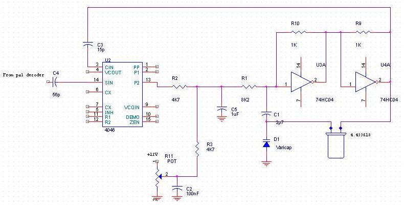
Pal decoder
After several years, the NMS8280 was utilized again for HAM radio purposes. When transmitting a signal, radio amateurs must always identify themselves by providing their callsign, which also applies to video signal transmission. A program was created using the WBASS...
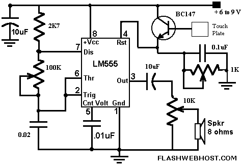
Morse Code with touch button (555)
This simple CPO is for those who want to practice Morse Code in a different way, ie without the morse key. It can be also used as a touch operated door bell. The popular timer IC555 is wired as an...
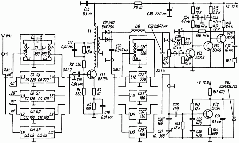
HAM RADIO SW RECEIVER
A simple radio receiver circuit is illustrated. This receiver is designed to capture signals from amateur radio stations operating in the shortwave (SW) bands of 10, 15, 20, 40, and 80 meters. The direct-conversion receiver comprises a set of input...
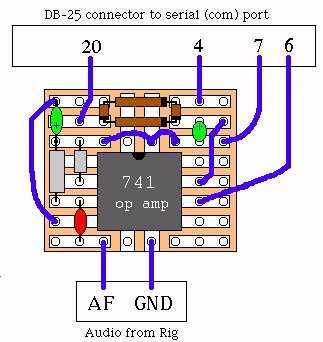
Ham radio Communication
It's a very easy interface to build and requires only a few £/$ worth of components. As you can see by the picture on the right, there's not much to it. To be honest, the picture is misleading. This hamcomm...
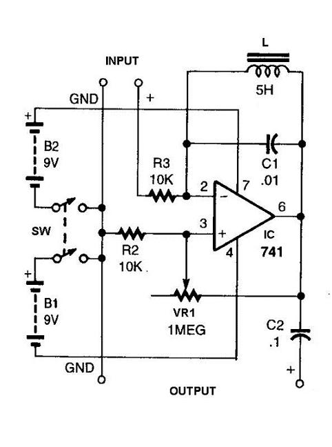
Simple Ham Radio Circuit Audio Filter With 741 IC
This circuit will filter out interference signals and ensure that the signal received from the Morse code station stands out.
The described circuit functions as a signal processing system specifically designed to enhance the clarity of Morse code transmissions by minimizing...
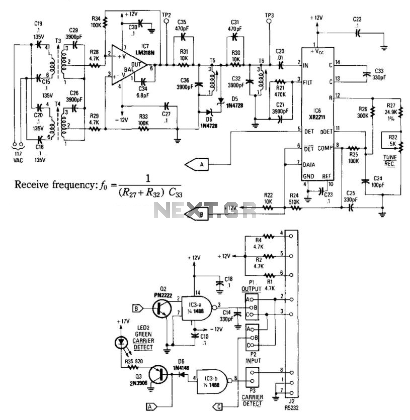
Carrier-Current Receiver For Data Transmission
This receiver consists of an input network, amplifier IC7, FSK PLL detector IC8, and output amplifier/interface circuits Q2, Q3, IC3A, and IC3B, which include a 1488 Quad RS232 line driver for the carrier-current signal. The tuned amplifier IC7 amplifies this...
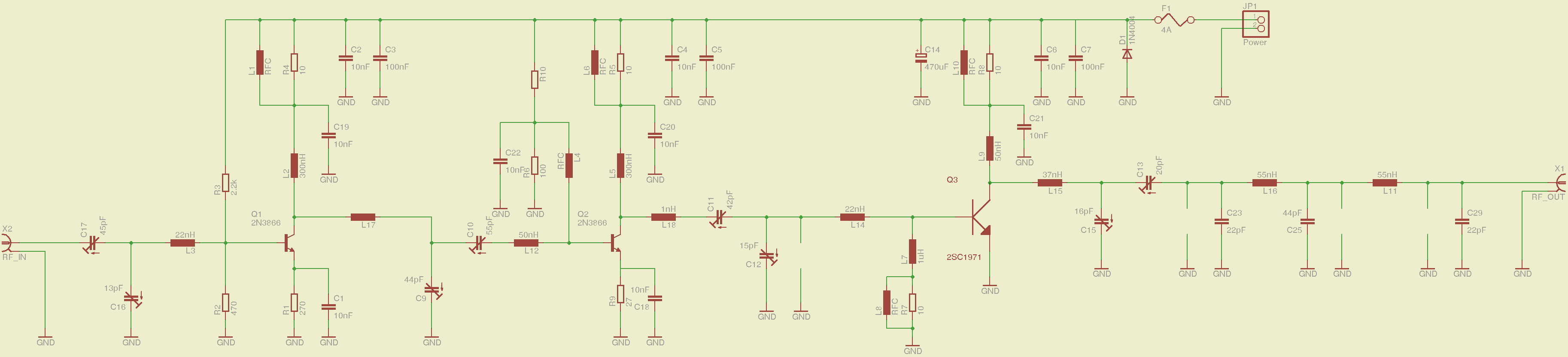
2meter 144mhz amateur radio transceiver
A 2-meter ham radio transceiver that incorporates all necessary circuitry, specifically including a voltage-controlled oscillator (VCO) and phase-locked loop (PLL) for frequency synthesis, a low noise amplifier (LNA) for the receiver front-end, a power amplifier (PA) for the radio frequency...
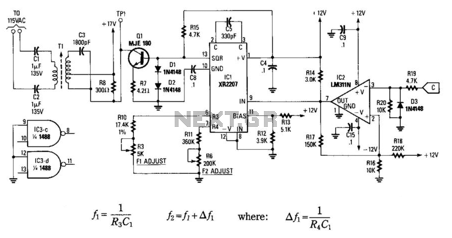
Carrier Current Transmitter For Data Transmission
In this circuit, data at input C is amplified by IC2 and then fed to modulator IC1. IC1 generates two frequencies, depending on the values of C5, I10, R5, Rn, and R6. The frequency f1 is generated if pin 9...